Supercharge Your Innovation With Domain-Expert AI Agents!

Backscatter uplink data collection method based on parallel decoding

A backscatter, line data technology, applied in the direction of link quality-based transmission modification, receiver-specific devices, digital transmission systems, etc., can solve problems such as low uplink data collection efficiency

Inactive Publication Date: 2019-12-13
山西警察学院
View PDF4 Cites 6 Cited by
  • Summary
  • Abstract
  • Description
  • Claims
  • Application Information

AI Technical Summary

Problems solved by technology

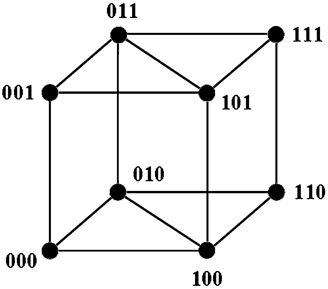
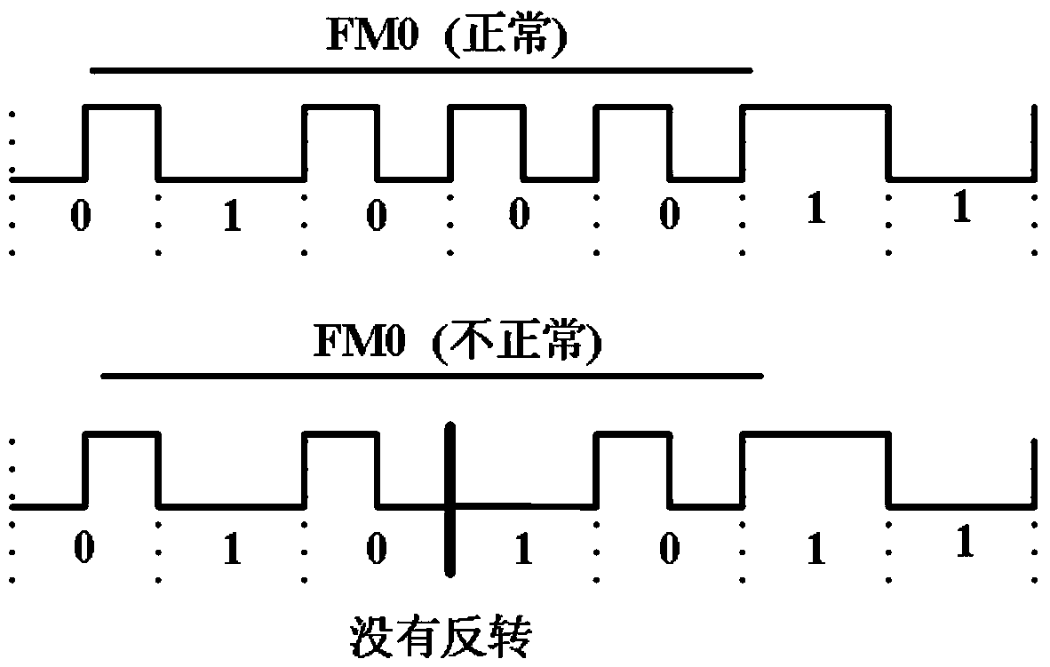
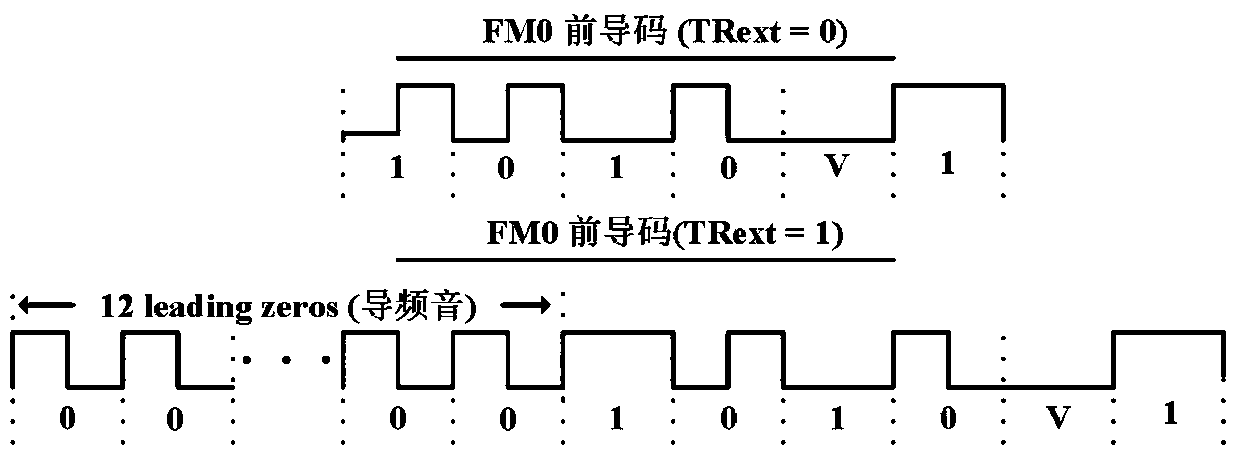
[0003] In order to solve the problem of low efficiency of uplink data collection in the existing backscatter system, the present invention proposes a backscatter uplink data collection method based on parallel decoding

Method used


Image

  • Backscatter uplink data collection method based on parallel decoding
  • Backscatter uplink data collection method based on parallel decoding
  • Backscatter uplink data collection method based on parallel decoding

Examples


Embodiment Construction

[0019] Below in conjunction with example and accompanying drawing, the inventive method is described in further detail:

[0020] A method for collecting backscatter uplink data based on parallel decoding comprises the following steps:

[0021] (1) In backscatter communication, the receiver provides energy supply for the passive node. When the receiver sends the carrier to communicate with the node, the carrier contains the I component and the Q component in the same direction. The node transmits the signal by absorbing or reflecting the carrier signal. The signal backscattered to the receiver still contains the same direction I component and the quadrature Q component. For a single node k, the signal received by the receiver is expressed as:

[0022]

[0023] in and Denote the codirectional component and the orthogonal component respectively. For N nodes transmitting data concurrently, the receiver receives the superposition of multiple node signals, expressed as:

[0...


PUM


Abstract

The invention relates to the field of backscatter uplink data collection, in particular to a backscatter uplink data collection method based on parallel decoding. In order to solve the problem that atraditional data collection protocol follows an EPC C1G2 protocol, the protocol allows only a single node to communicate with a receiver in a single time slot, and the data collection efficiency is low, the invention provides a backscattering uplink data collection method based on parallel decoding. According to the method, parallel transmission of a plurality of nodes in a single time slot is allowed; the receiver utilizes the physical layer information of the node to cluster the node state in combination with the cluster, and combines the node coding characteristics to correct the node information, so that the decoding efficiency of the receiver is improved, the parallel decoding transmission of the receiver for a plurality of nodes is realized, and the backscattering uplink data collection efficiency is improved.

Description

technical field [0001] The invention relates to a backscatter uplink data collection method, in particular to a backscatter uplink data collection method based on parallel decoding. Background technique [0002] In the existing backscatter communication system, the passive node itself does not carry power supply equipment, and the energy mainly comes from the receiver to supply energy to the carrier wave sent by the node, and the receiver uses the backscatter principle to communicate with the node. In order to avoid node communication conflicts, the existing data collection protocol follows the EPC C1G2 protocol, and a single node can only communicate with the receiver in a single time slot, which greatly limits the transmission rate of the node. It is inefficient for a single node to transmit information in a single time slot. One potential method is to allow multiple nodes to transmit data to the receiver in parallel in a single time slot, and the receiver decodes in paral...

Claims


Application Information

Patent Timeline
IPC IPC(8): H04L1/00
CPCH04L1/0036H04L1/0045
Inventor 朱飑凯刘三满张倩肖晋华
Owner 山西警察学院
Features
  • R&D
  • Intellectual Property
  • Life Sciences
  • Materials
  • Tech Scout
  • Unparalleled Data Quality
  • Higher Quality Content
  • 60% Fewer Hallucinations
Learn More