Supercharge Your Innovation With Domain-Expert AI Agents!

A multifunctional four-jaw chuck for machine tools

A four-jaw chuck, multi-functional technology, applied in the direction of the chuck, etc., can solve the problem of not being able to clamp elliptical and rectangular disc-shaped parts, etc.

Active Publication Date: 2020-10-02
盐城青松机械制造有限公司
View PDF9 Cites 0 Cited by
  • Summary
  • Abstract
  • Description
  • Claims
  • Application Information

AI Technical Summary

Problems solved by technology

[0002] The four-jaw chuck is one of the fixtures commonly used in machine tools. The traditional four-jaw chuck can only realize the single function of four-jaw automatic centering or non-automatic centering, and cannot clamp elliptical and rectangular disc-shaped parts. This invention solves the above problems

Method used


Image

  • A multifunctional four-jaw chuck for machine tools
  • A multifunctional four-jaw chuck for machine tools
  • A multifunctional four-jaw chuck for machine tools

Examples


specific Embodiment approach 1

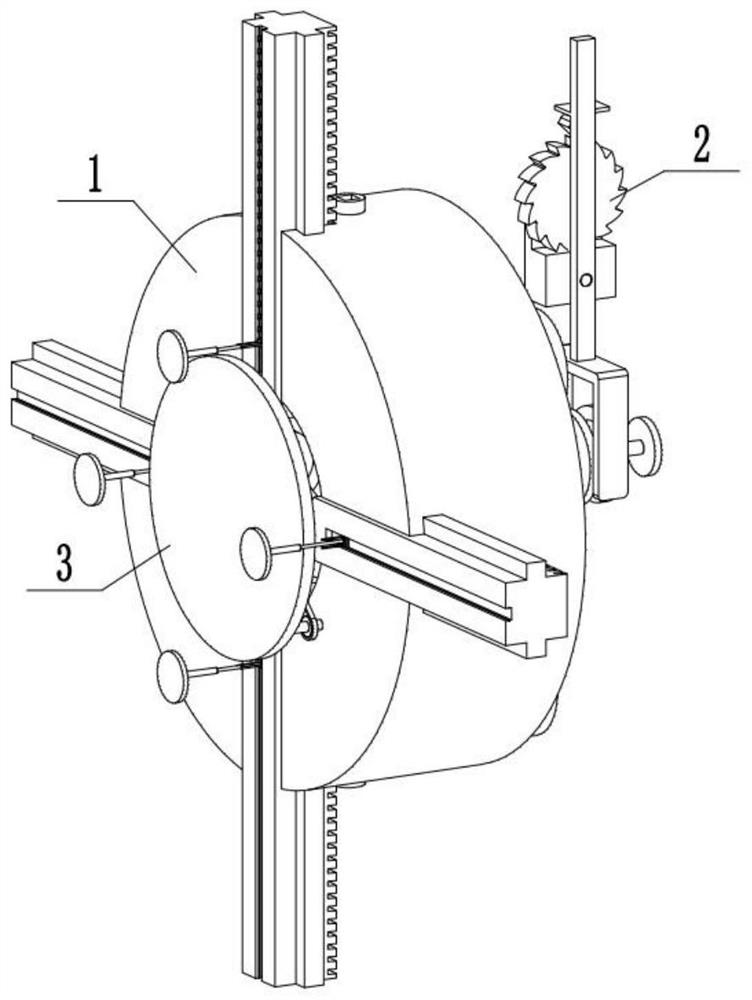
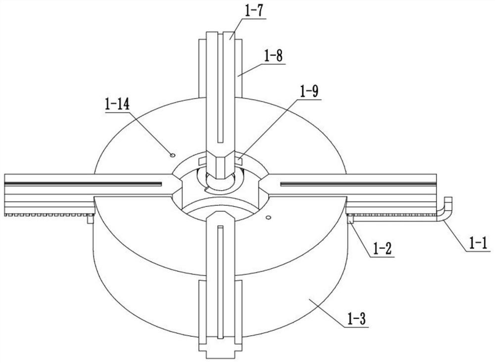
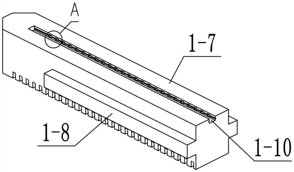
[0031] Combine below Figure 1-17 Describe this embodiment, a multifunctional four-jaw chuck for machine tools, including a clamping assembly 1, an adjusting assembly 2, and a disc-shaped part clamping assembly 3, and the clamping assembly 1 includes a square wrench 1- 1. Adjusting cylinder 1-2, fixture shell 1-3, bevel gear 1-4, helical gear shaft 1-5, helical tooth 1-6, claw 1-7, claw carriage 1-8, claw slide Rail 1-9, chute Ⅰ 1-10, positioning hole 1-11, chute Ⅱ 1-12, friction groove 1-13 and threaded through hole 1-14, square wrench 1-1 and four adjustment cylinders 1-2 all For clearance fit, the four adjusting cylinders 1-2 are all connected to the fixture shell 1-3 in rotation, the four adjusting cylinders 1-2 are respectively connected to the four bevel gears 1-4, and the four bevel gears 1-4 are respectively connected to the four bevel gears. The four helical tooth shafts 1-5 are connected to each other, the four helical tooth shafts 1-5 are respectively connected to ...

specific Embodiment approach 2

[0035] Combine below Figure 1-17 Describe this embodiment, this embodiment will further explain the first embodiment, the disc-shaped part clamping assembly 3 includes a lifting plate 3-1, a threaded shaft I3-2, a lifting knob 3-3, and a pulley I3-4 , belt 3-5, pulley Ⅱ 3-6, threaded shaft Ⅱ 3-7, transposition lever 3-8, slanting block 3-9, slanting block housing 3-10, spring Ⅲ 3-11, slanting block housing carriage 3- 12. The lower threaded column 3-13, the upper threaded cylinder 3-14 and the limit plate 3-15, the lifting plate 3-1 is rotationally connected with the threaded shaft Ⅰ 3-2, the threaded shaft Ⅱ 3-7, the threaded shaft Ⅰ 3-2, the threaded shaft Shaft II 3-7 is threadedly connected with two threaded through holes 1-14 respectively, lifting knob 3-3 and pulley I 3-4 are connected with threaded shaft I 3-2, pulley I 3-4, belt 3-5, belt The pulley II3-6 is connected with the belt pulley, the pulley II3-6 is connected with the threaded shaft II3-7, the eight transpo...


PUM


Abstract

The invention relates to the field of clamps, and specifically relates to a multifunctional four-jaw chuck for a machine tool. The multifunctional four-jaw chuck comprises a clamping assembly, an adjusting assembly and a disc-type part clamping assembly, the four-jaw chuck is one of the clamps commonly used in machine tools, a traditional four-jaw chuck can only realize automatic centering or non-automatic centering of four claws, an ellipse and a rectangular disc-shaped part cannot be clamped, and the multifunctional four-jaw chuck solves the above-mentioned problems. The handle is shifted torotate an angle of one ratchet tooth and limits, at this time, rotating the handle can simultaneously adjust the four jaws to simultaneously advance or retract simultaneously, automatic centering andclamping can be completed, the handle is shifted to rotate the angle of the two ratchet teeth and limits, at the moment, the position of each clamping jaw can be adjusted by using a four-angle wrench, clamping of a cylindrical material such as an ellipse, a rectangle and the like can be completed, the disc-type part clamping assembly can clamp the disc-shaped part conveniently and is convenient to disassemble and install, the clamping part can be quickly installed during application, and the clamping part can be quickly disassembled when not in use.

Description

technical field [0001] The invention relates to the field of fixtures, in particular to a multifunctional four-jaw chuck for machine tools. Background technique [0002] The four-jaw chuck is one of the fixtures commonly used in machine tools. The traditional four-jaw chuck can only realize the single function of four-jaw automatic centering or non-automatic centering, and cannot clamp elliptical and rectangular disc-shaped parts. This invention solves the above problems . Contents of the invention [0003] The purpose of the present invention is achieved through the following technical solutions: [0004] A multifunctional four-jaw chuck for machine tools, comprising a clamping assembly, an adjusting assembly, and a disc-shaped part clamping assembly, the clamping assembly includes a square wrench, an adjusting cylinder, a clamp shell, a bevel gear, a screw Gear shaft, helical tooth, claw, claw carriage, claw slide rail, chute Ⅰ, positioning hole, chute Ⅱ, friction groo...

Claims


Application Information

Patent Timeline
IPC IPC(8): B23B31/10B23B31/16
CPCB23B31/102B23B31/16B23B31/16283
Inventor 李彦双林梅芳
Owner 盐城青松机械制造有限公司
Features
  • R&D
  • Intellectual Property
  • Life Sciences
  • Materials
  • Tech Scout
  • Unparalleled Data Quality
  • Higher Quality Content
  • 60% Fewer Hallucinations
Learn More