Disc connecting mechanism with multi-shaft sleeve supporting, rotary drilling rig and working method for rotary drilling rig

A technology of connecting mechanism and shaft sleeve, applied in drilling equipment and methods, drilling equipment, earthwork drilling and other directions, can solve the problems of mast guidance deviation, unstable swing, affecting the normal use of rotary drilling rig, etc., to reduce shaking, The effect of improving swing stability

Pending Publication Date: 2019-12-17
XUZHOU XUGONG FOUND CONSTR MACHINERY
View PDF0 Cites 0 Cited by
  • Summary
  • Abstract
  • Description
  • Claims
  • Application Information

AI Technical Summary

Problems solved by technology

Especially when the drill mast is relatively long and heavy, its swing is unstable and the angle is difficult to control. It is easy to have

Method used


Image

  • Disc connecting mechanism with multi-shaft sleeve supporting, rotary drilling rig and working method for rotary drilling rig
  • Disc connecting mechanism with multi-shaft sleeve supporting, rotary drilling rig and working method for rotary drilling rig
  • Disc connecting mechanism with multi-shaft sleeve supporting, rotary drilling rig and working method for rotary drilling rig

Examples


Embodiment 1

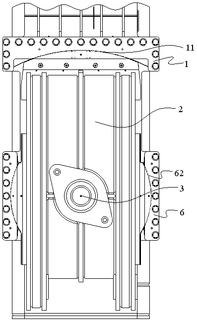
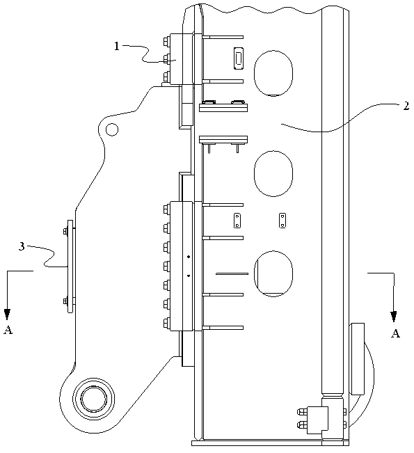
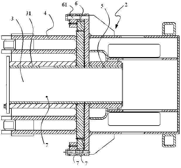
[0025] Such as figure 1 , figure 2 and image 3 As shown, the present embodiment 1 provides a disc connection mechanism supported by multi-axis sleeves, including: a support frame 1 with a concave arc surface 11 facing downward, a drill mast 2 whose top is against the concave arc surface 11, and a vertically inserted The mandrel 3 of the drill mast 2 and the large disk 4 that is sheathed on the mandrel 3; the large disk 4 is suitable for driving the drill mast 2 to rotate around the mandrel 3 when rotating, so that the top of the drill mast 2 moves along the The concave arc surface 11 moves, that is, the drill mast 2 swings left and right. Specifically, during use, the drill mast is generally arranged vertically, and the mandrel is arranged horizontally on the drill mast.

[0026] Optionally, the top of the drill mast 2 is adapted to the concave arc surface.

[0027] The disc connection mechanism in Embodiment 1 drives the large disc to rotate through the luffing mechanis...

Embodiment 2

[0036] On the basis of Embodiment 1, this Embodiment 2 provides a rotary drilling rig, including: a luffing mechanism and a disc connection mechanism as described above; wherein the luffing mechanism is hinged to the disc connection mechanism, so Drive the big disc to rotate.

[0037] For the specific structure and implementation process of the disk connection mechanism, please refer to the relevant discussion of Embodiment 1, and details will not be repeated here.

Embodiment 3

[0039] On the basis of embodiment 1, this embodiment 3 provides a working method of the disk connection mechanism, the large disk of the disk connection mechanism is suitable for driving the drill mast to rotate around the mandrel when rotating, so that The top of the drill mast moves along the concave arc surface of the support frame. Wherein the big disc can be driven to rotate by the luffing mechanism.

[0040] For the specific structure and implementation process of the disk connection mechanism, please refer to the relevant discussion of Embodiment 1, and details will not be repeated here.


PUM


Abstract

The invention discloses a disc connecting mechanism with multi-shaft sleeve supporting, a rotary drilling rig and a working method for the rotary drilling rig, wherein the disc connecting mechanism comprises a supporting frame provided with a concave arc surface, facing downwards, a drill mast with the top abutted against the concave arc surface, a mandrel vertically inserted into the drill mast and a large disc sleeved outsides the mandrel; and the large disc is suitable for driving the drill mast to rotate around the mandrel during rotation so as to enable the top of the drill mast to move along the concave arc surface. At the moment, a swing motion track of the drill mast takes the mandrel as a rotating shaft and the concave arc surface as a limiting surface, so that shaking of the drill mast in the swing process can be effectively lowered, and the swing stability of the drill mast is improved.

Description

technical field [0001] The invention relates to the field of machinery, in particular to a disc connection mechanism supported by multiple shaft sleeves, a rotary drilling rig and their working methods. Background technique [0002] Rotary drilling rig is a construction machine suitable for hole-forming operations in building foundation engineering. It is mainly suitable for construction in sandy soil, cohesive soil, silty soil and other soil layers. It is widely used in foundation construction such as cast-in-place piles, diaphragm walls, and foundation reinforcement. application. Its working principle is to quickly reach the pile position through the drilling rig's own walking function and mast luffing mechanism, use the mast to guide and lower the drill pipe, and place the cylindrical drill bit with a valve at the bottom to the hole position, and the power head device of the drilling rig To provide torque for the drill pipe, the pressurizing device transmits the pressuri...

Claims


Application Information

Patent Timeline
IPC IPC(8): E21B7/02
CPCE21B7/021
Inventor 王海金孙余耿倩斌魏亚坤刘丽娟
Owner XUZHOU XUGONG FOUND CONSTR MACHINERY
Why Eureka
Try Eureka