Arrangement for recirculating exhaust gas

A technology of exhaust gas recirculation and exhaust system, applied in the direction of exhaust gas recirculation, electrical control, charging system, etc., can solve the problem of material damage of the compressor, and achieve the effect of effective and safe droplet impact and high temperature

Pending Publication Date: 2019-12-17
FORD GLOBAL TECH LLC
View PDF0 Cites 0 Cited by
  • Summary
  • Abstract
  • Description
  • Claims
  • Application Information

AI Technical Summary

Problems solved by technology

The disadvantage of this strategy is that, at high discharge temperatures and large amounts of recirculated discharge gas, the materials of the compressor are loaded with high temperature and can be damaged

Method used


Image

  • Arrangement for recirculating exhaust gas
  • Arrangement for recirculating exhaust gas

Examples


Embodiment Construction

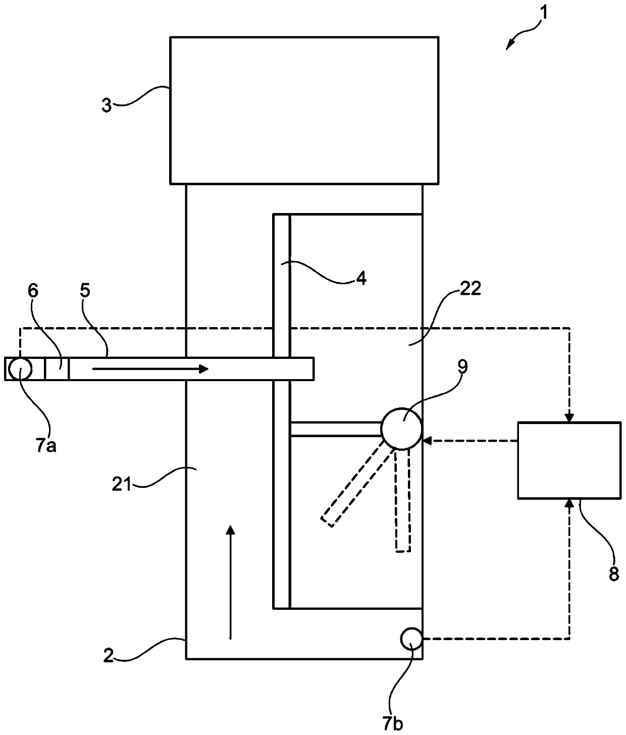
[0040] In one embodiment of arrangement 1 according to the invention, according to figure 1 , showing intake duct 2. Intake duct 2 delivers charge air to an internal combustion engine (not shown) of the motor vehicle. The compressor 3 compresses the charge air, which compressor 3 is provided in the flow path of the intake port 2 . Upstream of the compressor 3 , a partition wall 4 is provided in the intake duct, which divides the intake duct 2 into an outer tube 21 and an inner tube 22 in a defined portion ending immediately upstream of the compressor.

[0041] The walls of the inner tube 22 are formed by the partition wall 4 and the walls of the inlet duct 2 . In a preferred embodiment, the partition wall 4 is implemented so as to partially enclose the volume of the inner tube 22 . Therefore, the cross-section of the partition wall 4 is curved, ie curved in the flow direction of the exhaust gas. Alternatively, the cross section of the partition wall 4 can also be straight ...


PUM


Abstract

The invention relates to an arrangement for recirculating exhaust gas. An arrangement is provided with a low-pressure exhaust gas recirculation pipeline, and the low-pressure exhaust gas recirculationline branches off from an exhaust system, leads to an intake passage and includes a first valve, where the intake passage is longitudinally divided into an outer tube and an inner tube upstream of acompressor by a partition wall, where a second valve is disposed in the inner tube, and the exhaust line leads to the inner tube downstream of the second valve. Further, a method for controlling an amount of recirculated exhaust gas in a charge air flow is provided.

Description

technical field [0001] The invention relates to an arrangement for mixing recirculated exhaust gas and intake air in the opening region of an exhaust gas recirculation line in an intake tract of an internal combustion engine, as well as a motor vehicle with the arrangement and by means of the arrangement Methods. Background technique [0002] Exhaust gas recirculation systems (EGR systems) are used to reduce the emissions of nitrogen oxides produced during the combustion of fuel in internal combustion engines. To do this, exhaust gas is mixed with charge air and recirculated through the internal combustion engine. By mixing exhaust gas into intake air, its oxygen content is reduced, and with small fuel injections, the combustion temperature of the fuel-air mixture is reduced. Since the reaction rate of nitrogen oxide formation depends on the combustion temperature, less nitrogen oxides are formed at low combustion temperatures. [0003] With a low pressure (LP) EGR system...

Claims


Application Information

Patent Timeline
Patent Type & Authority Applications(China)
IPC IPC(8): F02M26/21F02M26/06
CPCF02M26/06F02M26/21F02D41/005F02D41/0065F02D2041/0067F02D2200/021F02D2200/0414F02D2200/0418F02D2200/101F02M26/19F02M26/50Y02T10/40
Inventor V·斯米利亚诺夫斯基J·克默林H·M·金德尔A·库斯克H·弗里德里希斯F·A·萨默候夫F·克拉默F·文德利希
Owner FORD GLOBAL TECH LLC
Why Eureka
Try Eureka