Quantitative system variable hydraulic system
A hydraulic system and system variable technology, applied in the direction of fluid pressure actuating device, servo motor, servo motor assembly, etc., can solve the problem of high work efficiency and energy consumption, reduce energy consumption, improve work efficiency and high energy consumption Effect
- Summary
- Abstract
- Description
- Claims
- Application Information
AI Technical Summary
Problems solved by technology
Method used
Image

Examples
Embodiment 1
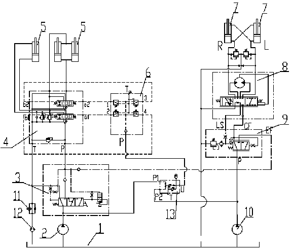
[0042] combine figure 1 As shown, a hydraulic system with variable quantitative system:
[0043] It includes a steering hydraulic cylinder 7 for driving the steering of the wheels, a second hydraulic pump 10 for providing hydraulic fluid to the steering hydraulic cylinder 7, a steering gear 8 for controlling the movement of the steering hydraulic cylinder 7, and providing priority for the steering gear 8. Priority valve 9 for flow rate.
[0044] The steering gear 8 has a first state in which the piston rod of the steering hydraulic cylinder 7 is extended and a second state in which the piston rod of the steering hydraulic cylinder 7 is retracted. The rodless chamber of the steering hydraulic cylinder communicates with the L port of the steering gear 8, and the rod chamber communicates with the R port of the steering gear 8. Therefore, when the piston rods of the two steering hydraulic cylinders extend, the piston of the other steering hydraulic cylinder The rod is retracted,...
Embodiment 2
[0079] The difference between the second embodiment and the first embodiment is:
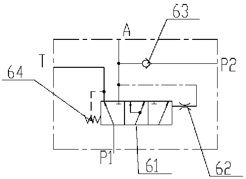
[0080] combine image 3 As shown, the control unloading valve 22 in the variable variable control valve 3 in the first embodiment is removed;
[0081] It works as follows:
[0082] When the working hydraulic cylinder 5 has no action or the load pressure is less than the predetermined value △P1;
[0083] The load pressure acts on the right end of the buffer valve 61 through the damping part IV62, the force of the spring I64 at the left end of the buffer valve 61 is greater than the load pressure, and the buffer valve 61 is in the first position, so that the fluid generated by the first hydraulic pump 2 passes through the variable control valve first. Outlet T flows to hydraulic tank 1. The effect is to make the first hydraulic pump 2 variable, avoiding the first hydraulic pump 2 and the second hydraulic pump 10 both working under high-power conditions, which is conducive to reducing the energy...
PUM
 Abstract
Description
Claims
Application Information
 - R&D
- Intellectual Property
- Life Sciences
- Materials
- Tech Scout
- Unparalleled Data Quality
- Higher Quality Content
- 60% Fewer Hallucinations
Browse by: Latest US Patents, China's latest patents, Technical Efficacy Thesaurus, Application Domain, Technology Topic, Popular Technical Reports.
© 2025 PatSnap. All rights reserved.Legal|Privacy policy|Modern Slavery Act Transparency Statement|Sitemap|About US| Contact US: help@patsnap.com