
Radio frequency isolation circuit and double-frequency network equipment

A technology for radio frequency isolation and network equipment, applied in electrical components, transmission systems, etc., can solve the problems of not meeting isolation requirements, poor interference suppression capability, narrow isolation bandwidth, etc., to reduce in-band insertion loss and improve interference suppression capability. Effect

Inactive Publication Date: 2019-12-17
TP-LINK
View PDF6 Cites 0 Cited by
  • Summary
  • Abstract
  • Description
  • Claims
  • Application Information

AI Technical Summary

Problems solved by technology

[0002] With the opening of the 6-7GHz frequency band (hereinafter referred to as the 6GHz frequency band), more and more network products will be designed to support the 6GHz frequency band. The isolation bandwidth is relatively narrow (about 100MHz). If it is necessary to simultaneously implement 5GHz frequency band and 6GHz frequency band operation on the network equipment, considering that the network equipment is generally small in size, the isolation between antennas cannot be too high, resulting in network equipment simultaneously. When working in the 5GHz frequency band and the 6GHz frequency band, there will be a lot of mutual interference
[0003] In response to the above problems, the general design is to use an isolation filter with large attenuation. However, the frequency interval between the 5GHz frequency band and the 6GHz frequency band is too narrow. There are two problems in the existing 5GHz and 6GHz isolation filters. One is that the 5GHz high The in-band insertion loss of the frequency band is too large, and the second is that the attenuation of the out-of-band 6GHz low frequency band is too small, which does not meet the isolation requirements, resulting in poor interference suppression capabilities

Method used


Image

  • Radio frequency isolation circuit and double-frequency network equipment
  • Radio frequency isolation circuit and double-frequency network equipment
  • Radio frequency isolation circuit and double-frequency network equipment

Examples


Embodiment Construction

[0037] The following will clearly and completely describe the technical solutions in the embodiments of the present invention with reference to the accompanying drawings in the embodiments of the present invention. Obviously, the described embodiments are only some, not all, embodiments of the present invention. Based on the embodiments of the present invention, all other embodiments obtained by persons of ordinary skill in the art without creative efforts fall within the protection scope of the present invention.

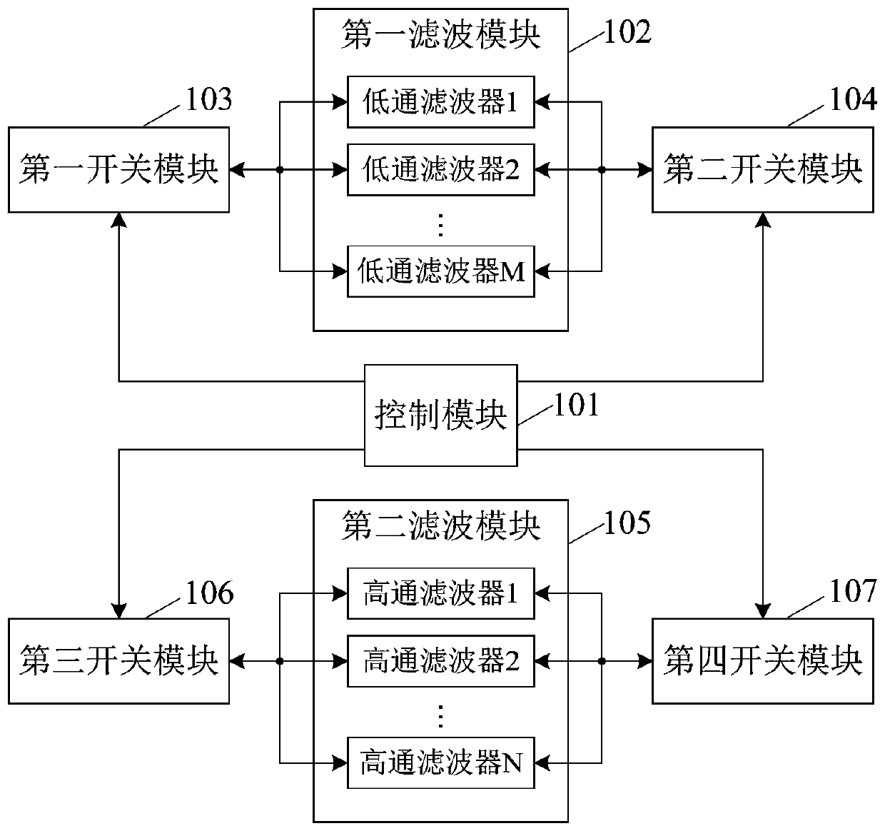
[0038] An embodiment of the present invention provides a radio frequency isolation circuit, see figure 1 Shown is a schematic structural diagram of a preferred embodiment of a radio frequency isolation circuit provided by the present invention, the circuit is suitable for dual-band network equipment; the circuit includes a control module 101, a first filter module 102, a first switch module 103. The second switch module 104, the second filter module 105, the third ...


PUM


Abstract

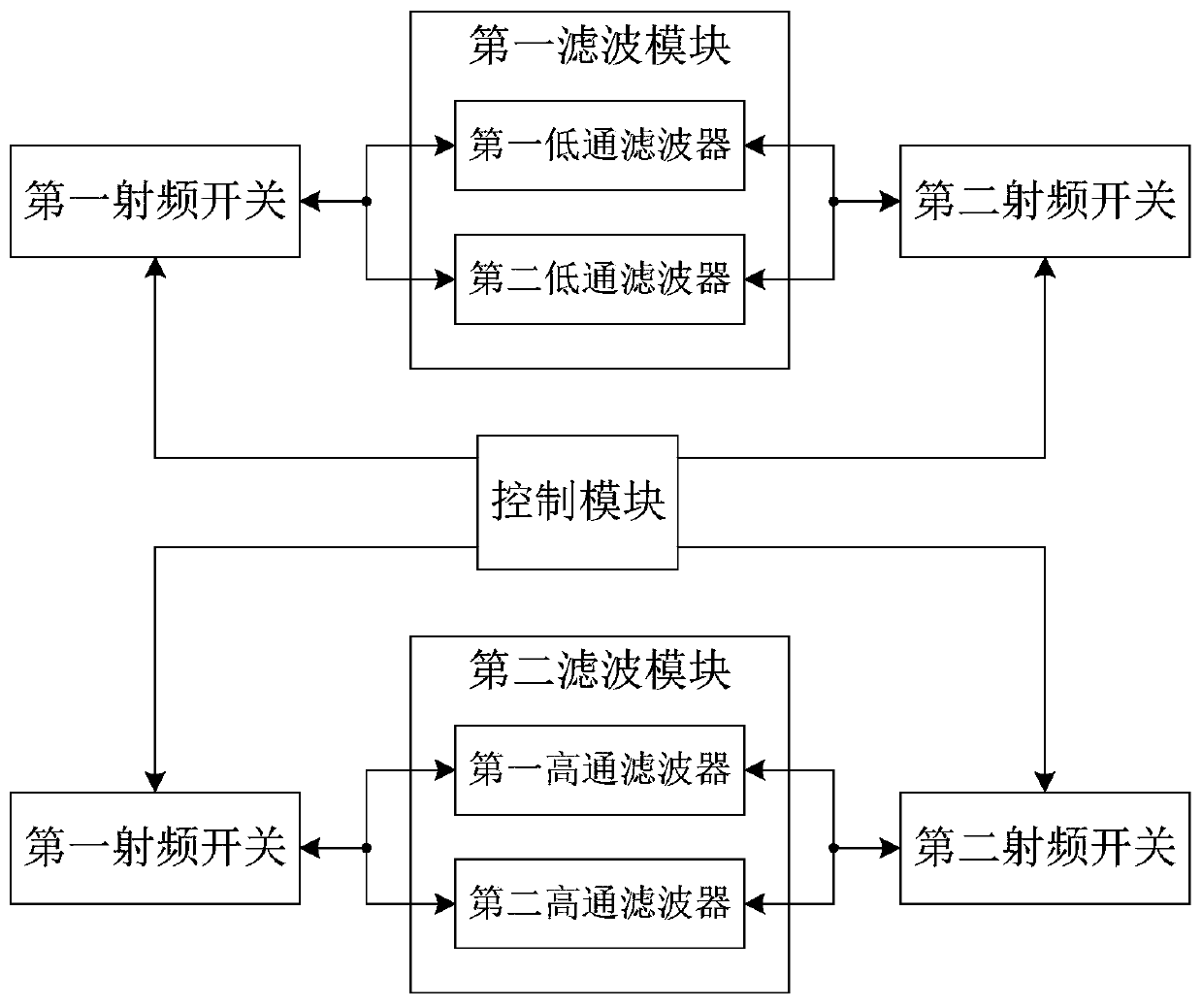
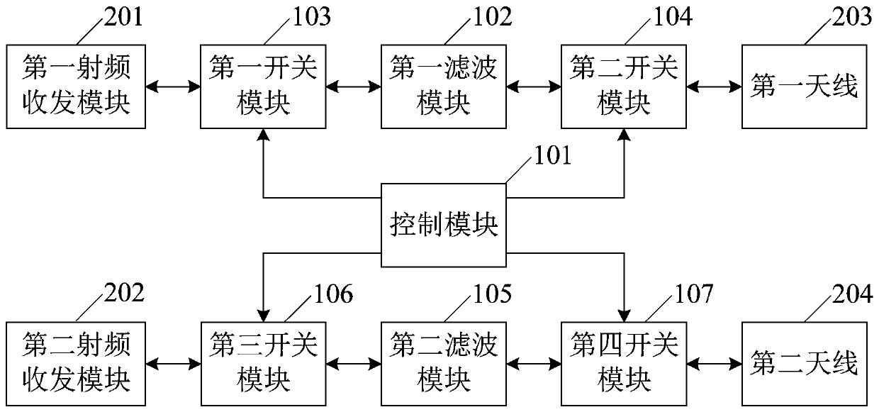
The invention discloses a radio frequency isolation circuit and double-frequency network equipment. The circuit comprises a control module, a first filtering module, a first switch module, a second switch module, a second filtering module, a third switch module and a fourth switch module; the control module is used for generating a first control signal and a second control signal; the first filtering module is connected between the first switch module and the second switch module and comprises M low-pass filters which are connected in parallel and have different cut-off frequencies; the firstswitch module and the second switch module are used for gating one low-pass filter in the first filter module by the first control signal; the second filtering module is connected between the third switch module and the fourth switch module and comprises N high-pass filters which are connected in parallel and have different cut-off frequencies; and the third switch module and the fourth switch module are used for gating one high-pass filter in the second filter module according to the second control signal. According to the invention, the in-band insertion loss of the radio frequency link canbe reduced, and the interference suppression capability is improved.

Description

technical field [0001] The invention relates to the technical field of wireless communication, in particular to a radio frequency isolation circuit and dual-frequency network equipment. Background technique [0002] With the opening of the 6-7GHz frequency band (hereinafter referred to as the 6GHz frequency band), more and more network products will be designed to support the 6GHz frequency band. The isolation bandwidth is relatively narrow (about 100MHz). If it is necessary to simultaneously implement 5GHz frequency band and 6GHz frequency band operation on the network equipment, considering that the network equipment is generally small in size, the isolation between antennas cannot be too high, resulting in network equipment simultaneously. When working in the 5GHz frequency band and the 6GHz frequency band, there will be a lot of mutual interference. [0003] In response to the above problems, the general design is to use an isolation filter with large attenuation. Howev...

Claims


Application Information

Patent Timeline
IPC IPC(8): H04B1/401H04B1/525
CPCH04B1/401H04B1/525
Inventor 程越
Owner TP-LINK
Learn More