A High Power Harmonic Suppression Filter Based on Rectangular Waveguide Structure

A harmonic suppression, rectangular waveguide technology, applied in waveguide-type devices, circuits, electrical components, etc., can solve the problems of large filter volume and limited power capacity, achieve strong suppression ability, meet application requirements, and small volume. Effect

Active Publication Date: 2021-07-30
SOUTHEAST UNIV
View PDF5 Cites 0 Cited by
  • Summary
  • Abstract
  • Description
  • Claims
  • Application Information

AI Technical Summary

Problems solved by technology

The step impedance transformer is used to connect the height-reducing waveguide and the standard waveguide, and the stop band can reach above 55GHz, but since the minimum waveguide gap is only 0.649mm, the power handling capacity is limited
In addition, due to the use of multi-order quarter-wavelength impedance converters, the size of the filter is relatively large
For the problem that the gap is too small to affect the power capacity of the filter, in 2010, people such as I.Arregui of Spain's Navarre Public University Public University of Navarre reported a low-pass filter for Ku band harmonic suppression [I, Arregui ,I,et al.Design method for satellite output multiplexer low-pass filters exhibiting spurious-freefrequency behavior and high-power operation[J].Microwave&Optical Technology Letters,2010,52(8):1724-1728.], using traditional folded waveguide filter The wide stopband performance is achieved by cascading the filter and the sinusoidal perturbation waveguide structure. This method avoids the use of micro-slot structures and effectively improves the power capacity, but the disadvantage is that the cascading of multiple structures makes the filter volume too large

Method used


Image

  • A High Power Harmonic Suppression Filter Based on Rectangular Waveguide Structure
  • A High Power Harmonic Suppression Filter Based on Rectangular Waveguide Structure
  • A High Power Harmonic Suppression Filter Based on Rectangular Waveguide Structure

Examples


Embodiment Construction

[0021] Below in conjunction with accompanying drawing, technical scheme of the present invention is described in further detail:

[0022] This invention may be embodied in many different forms and should not be construed as limited to the embodiments set forth herein. Rather, these embodiments are provided so that this disclosure will be thorough and complete, and will fully convey the scope of the invention to those skilled in the art.

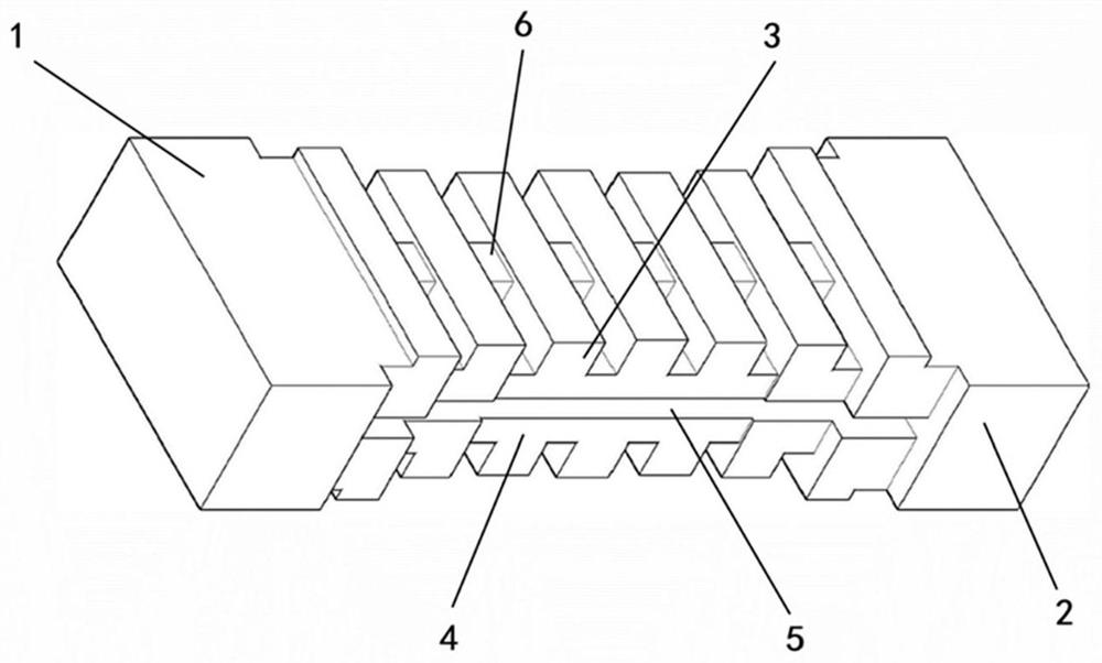
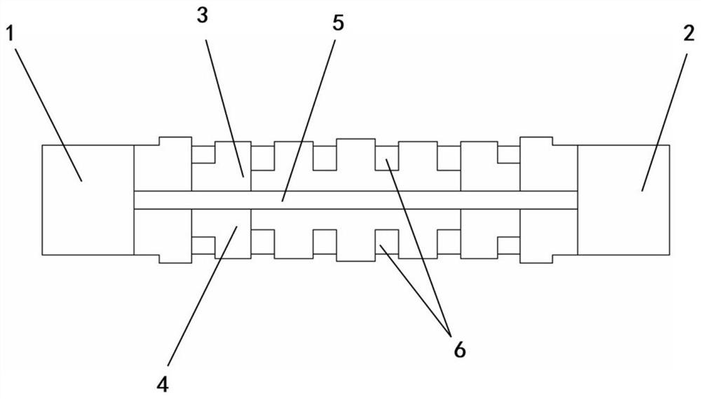
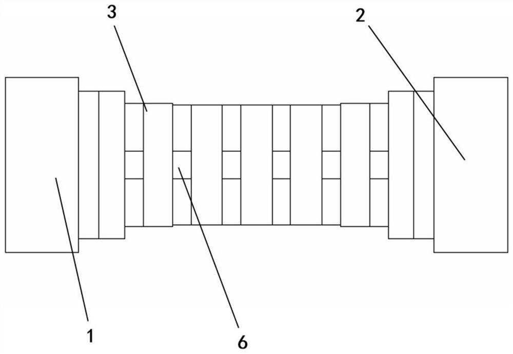
[0023] Such as figure 1 As shown, it is a structural schematic diagram of a high-power harmonic suppression filter based on a rectangular waveguide structure proposed by the present invention. The harmonic suppression filter includes,

[0024] A standard input waveguide 1, a standard output waveguide 2, a first harmonic suppression filter channel 3, a second harmonic suppression filter channel 4, and a metal sheet 5; wherein, the metal sheet 5 is arranged at the middle H surface of the rectangular waveguide, and The parallel surface of the ...


PUM


Abstract

The invention discloses a high-power harmonic suppression filter based on a rectangular waveguide structure, including a standard input waveguide, a standard output waveguide, a first harmonic suppression filter channel, a first harmonic suppression filter channel and a metal sheet; wherein, The metal sheet is arranged at the position of the H-plane in the middle of the rectangular waveguide. The first harmonic suppression filter channel and the second harmonic suppression filter channel are completely identical, and are arranged on both sides of the metal sheet in mirror symmetry. In the present invention, the harmonic suppression filter channel is realized by the corrugated waveguide low-pass filter structure, which avoids the tiny gap structure, improves the power capacity, and increases the filter stopband bandwidth through the mirror symmetry setting of the harmonic suppression filter channel. The central axis of the standard input / output waveguide and the central axis of the harmonic suppression filter channel are on the same straight line. In the microwave and millimeter wave frequency range, the second harmonic suppression waveguide filter with compact structure and low loss is realized. in high power amplifiers.

Description

technical field [0001] The invention relates to the technical field of waveguide filters, in particular to a high-power harmonic suppression filter based on a rectangular waveguide structure. Background technique [0002] Satellite communication has the advantages of large coverage, long communication distance, convenient networking, and no environmental restrictions. It is the main means of medium and long-distance communication. With the increasing demand for data, video, communication and control in satellite communication, the output power requirements of transmitters are also getting higher and higher. In order to increase the output power, the high-power amplifier in the transmitter usually works near the P1dB compression point, or even works in a saturated state. This also means that the amplifier produces relatively large harmonic signals, with the second harmonic being the largest. Due to the high output power of the amplifier, even though the harmonic signal is s...

Claims


Application Information

Patent Timeline
Patent Type & Authority Patents(China)
IPC IPC(8): H01P1/212
CPCH01P1/212
Inventor 许正彬钱澄徐杰
Owner SOUTHEAST UNIV
Why Eureka
Try Eureka