E-band high rejection bandpass filter based on ltcc

A band-pass filter and high-rejection technology, applied in the microwave field, can solve problems such as difficulties and increased manufacturing costs, and achieve the effects of reduced processing difficulty, low insertion loss, and easy implementation

Inactive Publication Date: 2017-01-25
NANJING UNIV OF SCI & TECH
View PDF6 Cites 0 Cited by
  • Summary
  • Abstract
  • Description
  • Claims
  • Application Information

AI Technical Summary

Problems solved by technology

However, the higher the integration, the sharper the manufacturing cost. Coupled with some limitations of materials and process technology, it is still very difficult to integrate all passive components into the IC.

Method used


Image

  • E-band high rejection bandpass filter based on ltcc
  • E-band high rejection bandpass filter based on ltcc
  • E-band high rejection bandpass filter based on ltcc

Examples


Embodiment 1

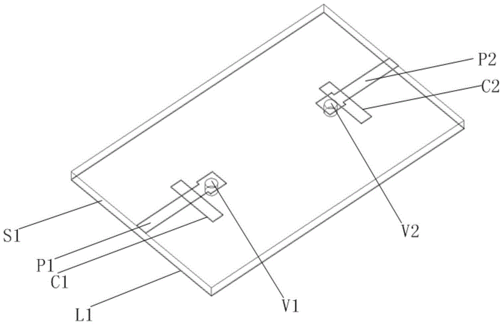
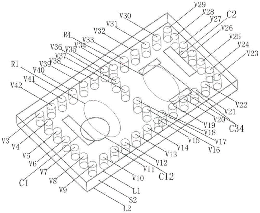
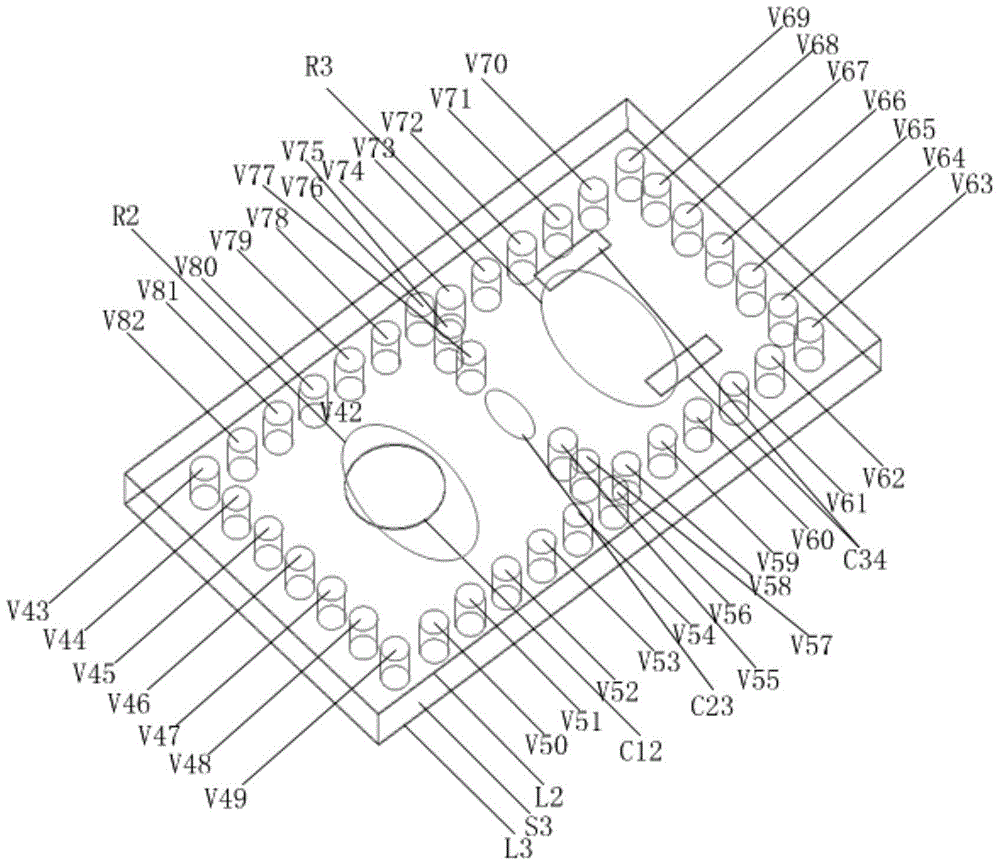
[0023] The relative dielectric constant of the ceramic substrate of the E-band high-suppression bandpass filter based on LTCC of the present invention is 6.8, the loss tangent is 0.002, the size is 2.8mm*1.6mm*0.52mm, and the radius of the metallized through hole is 0.06mm. The thickness of the metal wall on the surface of the ceramic substrate is 0.01 mm, the thickness of the first dielectric layer is 0.1 mm, the thickness of the second dielectric layer is 0.2 mm, and the thickness of the third dielectric layer is 0.2 mm. Depend on Figure 5 It can be seen that the minimum insertion loss in the passband is 2.1dB, the return loss is less than 18.11dB, the bandwidth is 71GHz to 76GHz, the lower sideband 67GHz suppression is better than 55dB, and the upper sideband 81GHz suppression is better than 56dB.

[0024] In summary, the frequency band of the present invention is the E-band, which has outstanding advantages such as wide frequency coverage, small insertion loss, good frequ...


PUM


Abstract

The invention discloses an LTCC (low temperature co fired ceramic) based E-band high-suppression band-pass filter which comprises three layers of ceramic substrate, a first metal layer with two coupling slots, a second metal layer with two coupling slots, a third metal layer, eighty-two metalized through holes, four resonant cavities, a first coupling slot, a second coupling slot, a third coupling slot, an input port and an output port. The four resonant cavities are respectively formed by eighty metalized through holes, the second layer of ceramic substrate and the third layer of ceramic substrate; the first coupling slot is formed between the first resonant cavity and the second resonant cavity, the second coupling slot is formed between the second resonant cavity and the third resonant cavity, and the third coupling slot is formed between the third resonant cavity and the fourth resonant cavity; the input port is formed by the first layer of ceramic substrate and the first metalized through hole, and the output port is formed by the first layer of ceramic substrate and the second metalized through hole. The LTCC based E-band high-suppression band-pass filter has the advantages of wide coverage of band and frequency, low insertion loss, good frequency selectivity, good resonance suppression characteristics, simple circuit structure, high controllability and the like and has excellent application prospect in the future high-rate data wireless communication.

Description

technical field [0001] The invention belongs to the field of microwave technology, and relates to a band-pass filter applied to microwave and millimeter-wave circuits, in particular to an LTCC-based E-band high-suppression band-pass filter. Background technique [0002] With the rapid development of wireless communication, the urgent requirements for microwave and millimeter wave systems are smaller size, faster speed, higher frequency and better performance. Band-pass filter is one of the most important passive devices in wireless communication radio frequency system, and the problems of miniaturization, high frequency and high frequency selectivity are becoming more and more prominent. Bandpass filter is one of the most important passive components in microwave and millimeter wave communication systems. A filter with excellent performance can better improve the signal-to-noise ratio of the system and provide better isolation between channels. Achieving a more reliable com...

Claims


Application Information

Patent Timeline
Patent Type & Authority Patents(China)
IPC IPC(8): H01P1/208
Inventor 戴永胜陈龙周围许心影顾家
Owner NANJING UNIV OF SCI & TECH
Why Eureka
Try Eureka