

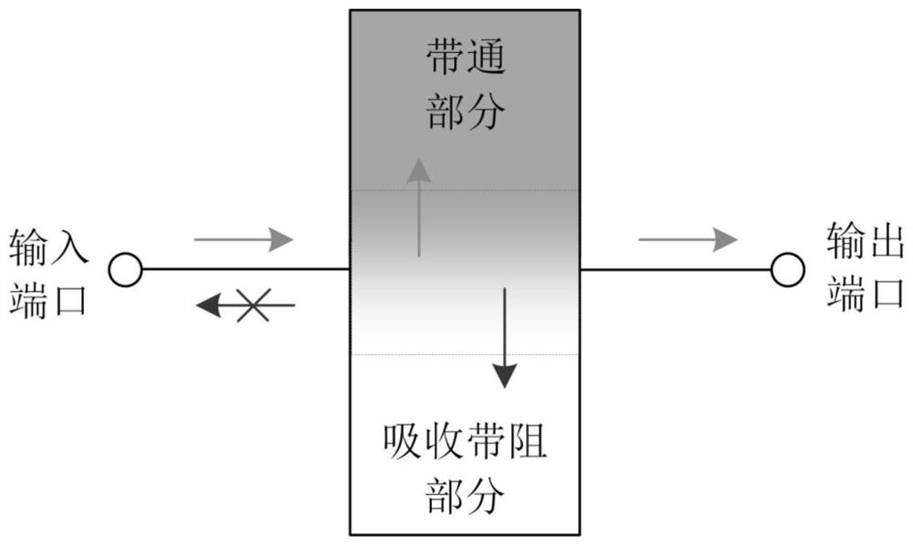
Balanced non-reflection band-pass filter
A band-pass filter, filter technology, applied in the direction of waveguide-type devices, circuits, electrical components, etc., can solve the problem of excessive design size, limited non-reflection bandwidth, and no detailed discussion of the band-pass part of the differential mode band-pass filter. Bandwidth relationship and other issues, to achieve the effect of compact circuit size, easy design parameter optimization, and low in-band insertion loss
- Summary
- Abstract
- Description
- Claims
- Application Information
AI Technical Summary
Problems solved by technology
Method used
Image

Examples
Embodiment Construction
[0047] The present invention will be further described below in conjunction with the accompanying drawings and specific embodiments.
[0048] In order to have a clearer understanding of the technical features, purposes and effects of the present invention, the specific implementation manners of the present invention will now be described in detail with reference to the accompanying drawings.
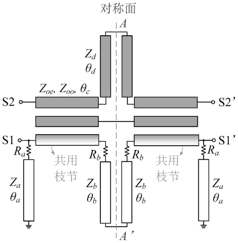
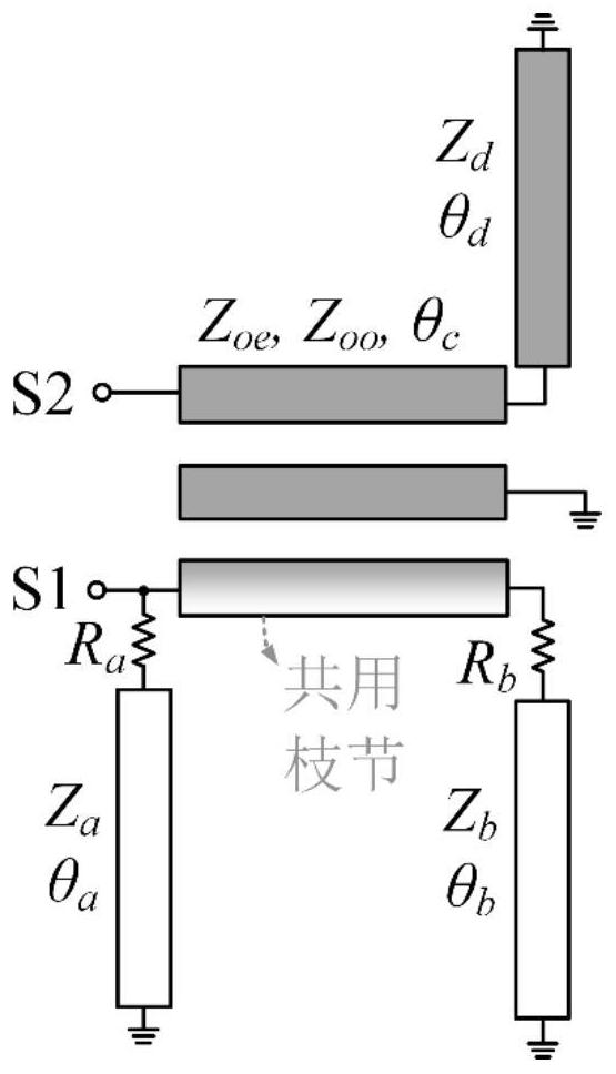
[0049] see Figure 18 is a top perspective view of a balanced non-reflection bandpass filter implemented in the present invention. The filter implemented in the present invention is composed of an upper metal strip, an intermediate dielectric substrate and a lower metal ground, including a differential bandpass filter and an absorption network, and the absorption network and the bandpass filter are arranged on the upper metal strip.
[0050] Among them, the differential bandpass filter is a symmetrical three-wire coupling structure, including a pair of differential input ports S1, S1' s...
PUM
 Abstract
Description
Claims
Application Information