
Modulator, demodulator and wireless communication system

A modulator and demodulator technology, which is applied in the modulation carrier system, phase modulation carrier system, transmission system, etc., can solve the phase ambiguity of the received signal, achieve the effect of precise modulation transmission and reception demodulation, and solve the phase ambiguity

Active Publication Date: 2019-12-17
SHANGHAI PANCHIP MICROELECTRONICS CO LTD
View PDF2 Cites 12 Cited by
  • Summary
  • Abstract
  • Description
  • Claims
  • Application Information

AI Technical Summary

Problems solved by technology

[0005] The embodiment of the present invention solves the problem of phase ambiguity of the received signal, and realizes the transmission modulation and reception demodulation of the multi-ary chirp signal

Method used


Image

  • Modulator, demodulator and wireless communication system
  • Modulator, demodulator and wireless communication system
  • Modulator, demodulator and wireless communication system

Examples


Embodiment Construction

[0021] In the multi-ary chirp modulation method in the existing related art, since the initial phase of the carrier of the received signal is unknown, the phase of the received signal is ambiguous, and it is impossible to estimate the initial phase of the actual transmitted signal, so it is impossible to judge the transmitted multi-ary modulation data.

[0022] The modulator used in the embodiment of the present invention generates the target chirp signal, can obtain the initial phase, can solve the problem of phase ambiguity, and enables more accurate modulation, transmission, reception and demodulation of the chirp signal.

[0023] In order to make the above objects, features and beneficial effects of the present invention more comprehensible, specific embodiments of the present invention will be described in detail below in conjunction with the accompanying drawings.

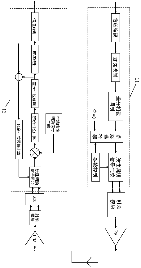
[0024] refer to figure 1 , an embodiment of the present invention provides a wireless communication syste...


PUM


Abstract

The embodiment of the invention provides a modulator, which comprises: a channel coding module for carrying out channel coding on data needing to be sent;; a multi-system digital phase modulation module which is used for carrying out modulation mapping on the data after channel coding and obtaining corresponding phase data; a differential phase modulation module which is used for modulating the phase data into an initial phase; and a chirp signal generation module which is used for generating a target chirp signal according to the initial phase. By adopting the modulator to generate the targetchirp signal, an initial phase can be obtained, the problem of phase ambiguity can be solved, and the chirp signal can be modulated, transmitted, received and demodulated more accurately.

Description

technical field [0001] The invention relates to the technical field of communication, in particular to a modulator, a demodulator and a wireless communication system. Background technique [0002] In the digital communication system, the binary or multi-ary modulation of the communication signal is realized by changing the amplitude, phase or frequency of the signal within the signal symbol period. The AM amplitude modulation signal realizes amplitude modulation, while the FM frequency modulation signal realizes modulation of frequency. Chirp (linear frequency modulation signal) modulation signal is a kind of spread spectrum modulation signal formed by the monotonous change of frequency with time according to a specific law for a period of time, which belongs to frequency modulation signal. [0003] Linear frequency modulation technology was applied to communication in 1962, and it expresses modulation information with different Chirp rates within the same symbol period. T...

Claims


Application Information

Patent Timeline
Patent Type & Authority Applications(China)
IPC IPC(8): H04L1/00H04L27/00H04L27/20H04L27/22
CPCH04L1/0009H04L27/20H04L27/22H04L27/0014H04L2027/0026H04B1/69H04B2001/6912H04L27/103H04L1/0041H04L1/0045
Inventor 阚伟伟吴川吴司熠
Owner SHANGHAI PANCHIP MICROELECTRONICS CO LTD
Learn More