Unmanned aerial vehicle sound source orientation device and method based on rotary cross array

A cross array and orientation device technology, which is applied in the direction of measuring devices, positioning, motor vehicles, etc., can solve the problems of orientation error and inaccurate orientation, and achieve the effect of low cost, small amount of calculation, and phase ambiguity

Active Publication Date: 2020-07-31
BEIHANG UNIV
View PDF9 Cites 1 Cited by
  • Summary
  • Abstract
  • Description
  • Claims
  • Application Information

AI Technical Summary

Problems solved by technology

In order to improve the resolution, the existing sound source orientation technology will use a large number of microphones or there may be some blind spots during orientation. When the drone approaches from these areas, the orientation will be inaccurate or even erroneous.

Method used


Image

  • Unmanned aerial vehicle sound source orientation device and method based on rotary cross array
  • Unmanned aerial vehicle sound source orientation device and method based on rotary cross array
  • Unmanned aerial vehicle sound source orientation device and method based on rotary cross array

Examples


Embodiment 1

[0039] Embodiment 1 (UAV sound source directional device)

[0040] This embodiment provides a drone sound source orientation device, which can perform two-dimensional real-time orientation on the position of the drone.

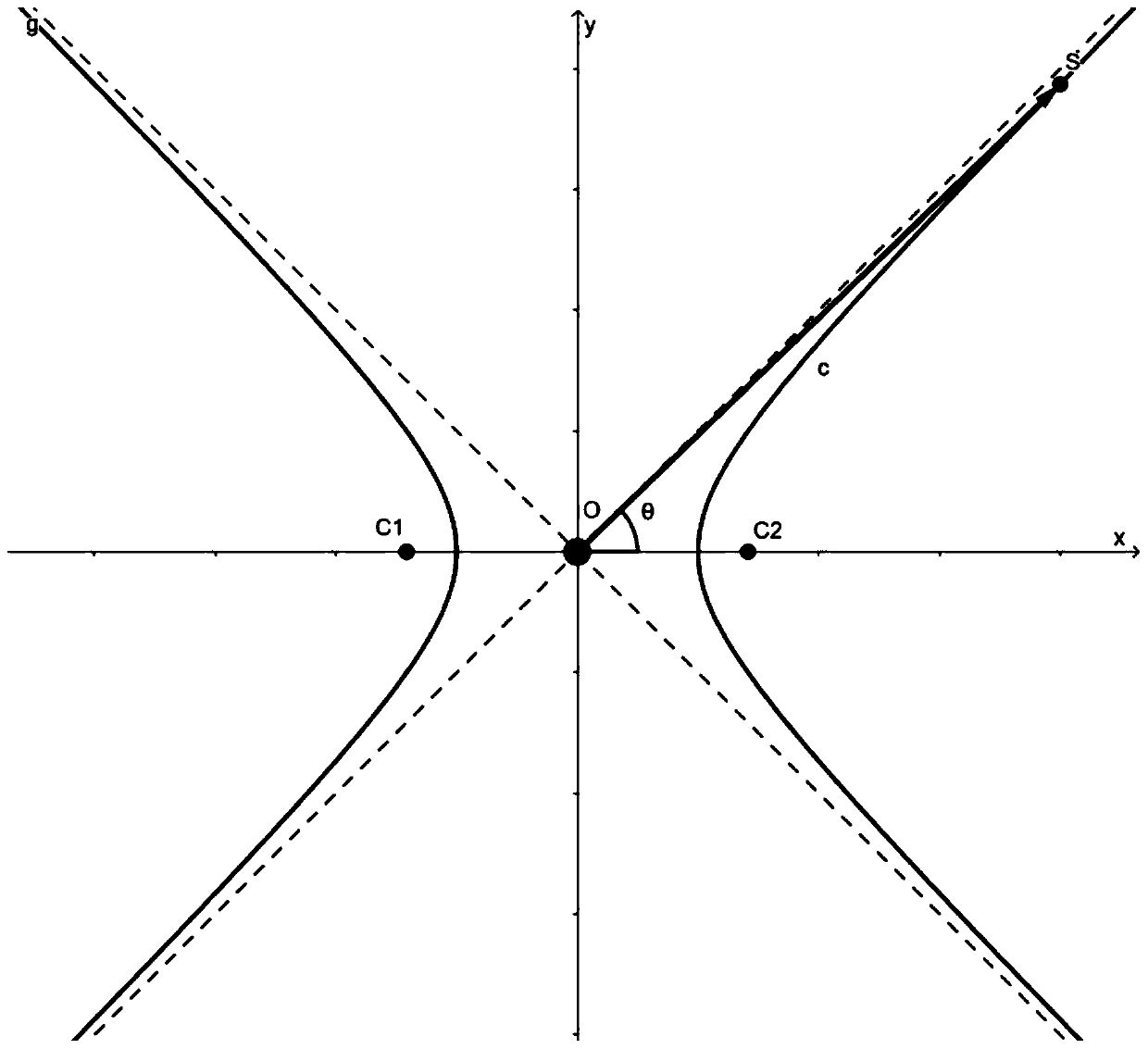
[0041] The principle of this embodiment is: collect the sound pressure signal (original signal) in the time domain generated when the UAV is flying, and perform upsampling and filtering, and obtain the time delay τ by retrieving the peak value of the cross-correlation function 1,2 , using the hyperbolic approximation model to obtain the horizontal deflection angle and pitch deflection angle, and finally the two-degree-of-freedom steering device aligns the cross array containing the microphones to the sound source of the drone.

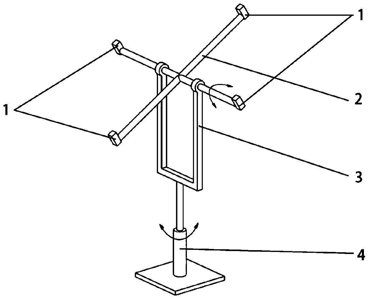
[0042] Such as figure 1 Shown, a kind of unmanned aerial vehicle sound source directional device, it comprises: cross array 2, two groups of microphones 1 (that is four microphones), processing device, two-degree-of-freedom steering d...

Embodiment 2

[0052] Embodiment 2 (UAV sound source orientation method)

[0053] This embodiment provides a method for orienting a sound source of a drone, which uses the device for orienting a sound source of a drone in Embodiment 1 to orient the drone.

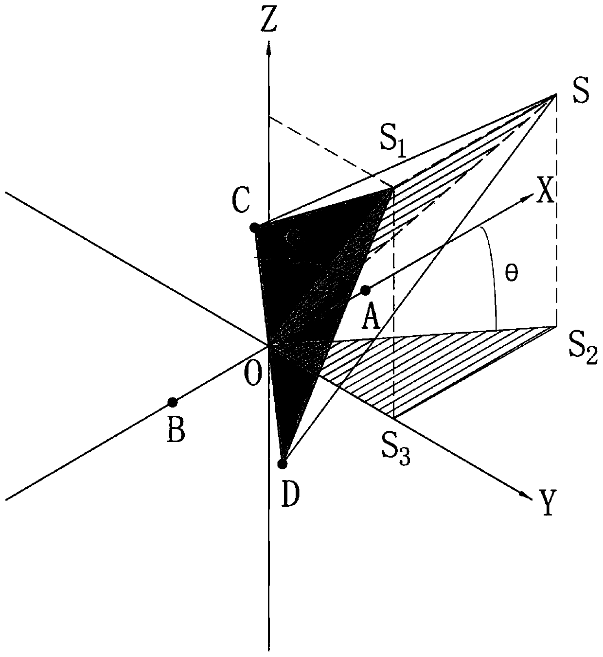
[0054] The principle of this embodiment is as figure 2 shown. Assume that microphone A and microphone B (belonging to one pair of microphones facing each other, set as the first group) are located on the X-axis (the line where AB is located is the X-axis, that is, no matter how the rotating cross rotates, it is always on the line where AB is located) is the X-axis for subsequent calculations), microphone C and microphone D (belonging to another pair of microphones facing oppositely, set as the second group) are located in the YOZ plane (including Y-axis and Z-axis, X-axis, Y-axis and The Z axes are perpendicular to each other, and the origin is O, so microphone C and microphone D can rotate around the X axis in the YOZ plane). The ori...


PUM


Abstract

The invention provides an unmanned aerial vehicle sound source orientation device and orientation method. The device comprises a cross array, four microphones, a processing device and a two-degree-of-freedom steering device. The four microphones are respectively located at four end points of the cross array and are used for collecting time domain sound pressure signals of the unmanned aerial vehicle, the processing device is used for calculating a horizontal deflection angle and a pitching deflection angle of the cross array, and the two-degree-of-freedom steering device is used for controlling the cross array to rotate correspondingly so as to be aligned with the unmanned aerial vehicle. The method comprises the following steps: acquiring a time domain sound pressure signal of the unmanned aerial vehicle by using a microphone, calculating a horizontal deflection angle and a pitching deflection angle of the cross array by using a processing device, and controlling the cross array to rotate by using a two-degree-of-freedom steering device. According to the unmanned aerial vehicle sound source orienting device and orienting method, only four microphones are used, and the cost is low.360-degree dead-corner-free orientation can be achieved through rotation, the optimal resolution can be achieved in any direction, the overall algorithm calculation amount is small, and response is fast.

Description

technical field [0001] The disclosure belongs to the technical field of sound source orientation, and relates to a drone sound source orientation device and an orientation method. Background technique [0002] In recent years, the rapid development of drone technology has brought great negative impacts while being widely used in various industries. For example, UAVs encroach on air routes and interfere with flight; UAVs invade important areas such as government and enterprise agencies, and invade privacy. Traditional security supervision mainly relies on ground video surveillance networks, and low-altitude security capabilities are relatively lagging behind, making it difficult to deal with illegal activities using drones as carriers. [0003] In order to detect and intercept UAVs, there are currently domestic methods for detecting UAVs based on technologies such as radar, image recognition, and wireless signals, but these methods have limitations to varying degrees. [00...

Claims


Application Information

Patent Timeline
Patent Type & Authority Applications(China)
IPC IPC(8): G01S5/18B64C39/02B64D47/00
CPCG01S5/18B64C39/02B64D47/00Y02T90/00
Inventor 杜林张吉孙晓峰景晓东王晓宇孙大坤
Owner BEIHANG UNIV
Why Eureka
Try Eureka