Supercharge Your Innovation With Domain-Expert AI Agents!

Driving source circuit

A driving circuit and driving source technology, applied in the field of quantum communication, can solve the problems of increasing signal jitter, affecting the performance of the voltage source impedance QKD system, etc., to avoid jitter, improve driving performance, and reduce difficulty.

Active Publication Date: 2019-12-17
QUANTUMCTEK
View PDF5 Cites 3 Cited by
  • Summary
  • Abstract
  • Description
  • Claims
  • Application Information

AI Technical Summary

Problems solved by technology

[0004] In view of the above-mentioned shortcomings of the prior art, the embodiment of the present invention provides a driving source circuit for solving the problem of pulse voltage driving in the prior art. The resulting signal jitter becomes larger, which affects the voltage source impedance and the performance of the QKD system

Method used


Image

  • Driving source circuit
  • Driving source circuit
  • Driving source circuit

Examples


Embodiment Construction

[0038] Embodiments of the present invention are described below through specific examples, and those skilled in the art can easily understand other advantages and effects of the present invention from the content disclosed in this specification. The present invention can also be implemented or applied through other different specific implementation modes, and various modifications or changes can be made to the details in this specification based on different viewpoints and applications without departing from the spirit of the present invention. It should be noted that, in the case of no conflict, the following embodiments and features in the embodiments can be combined with each other.

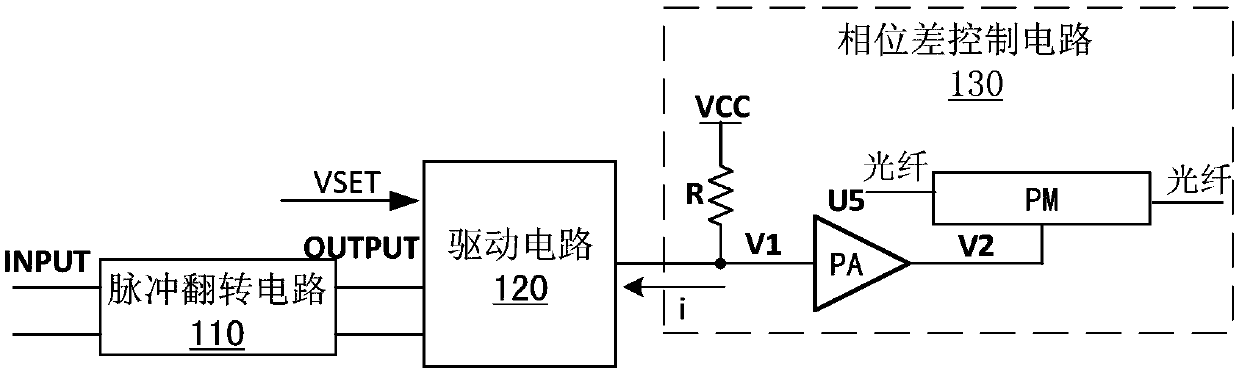
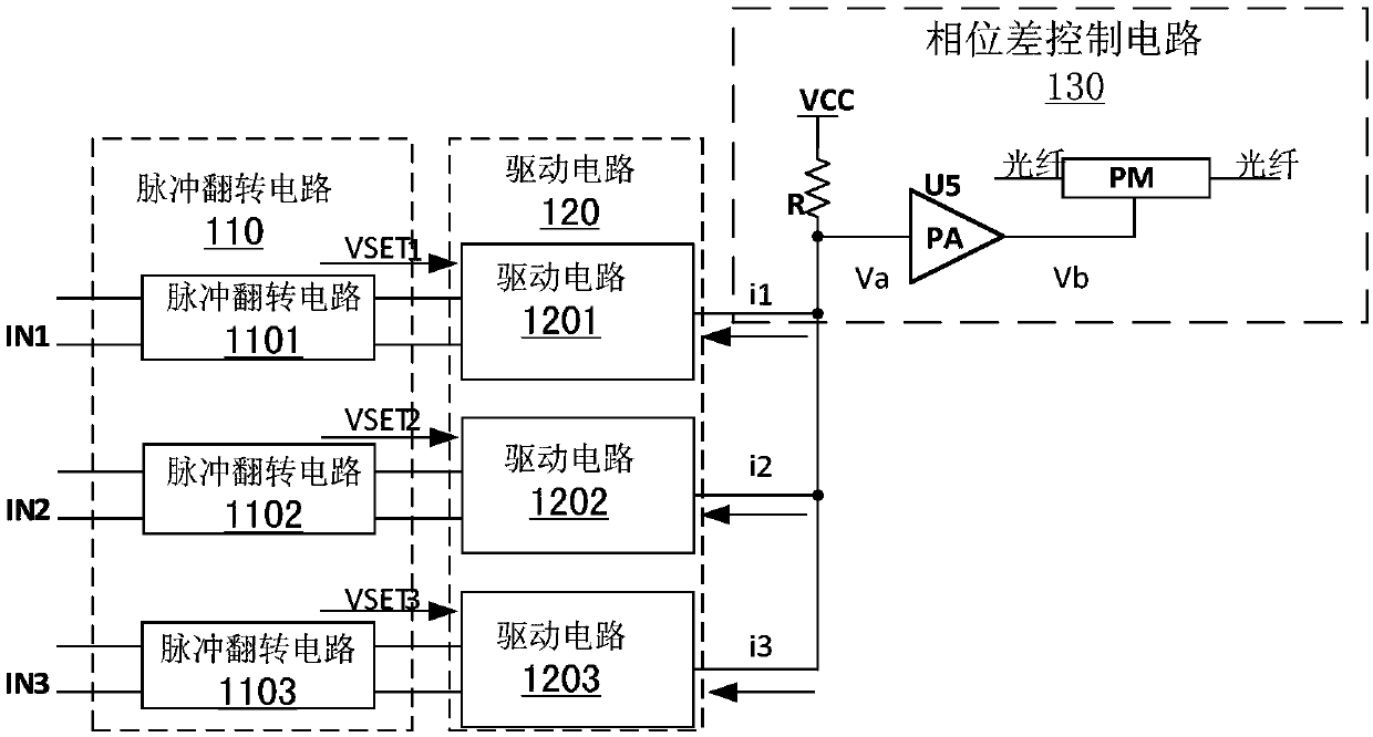
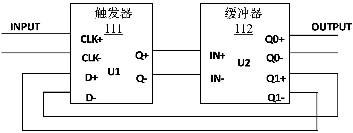
[0039] see Figure 1 to Figure 7 . It should be noted that the structures, proportions, sizes, etc. shown in the drawings attached to this specification are only used to match the content disclosed in the specification, for those who are familiar with this technology to understand and read, a...


PUM


Abstract

The invention provides a driving source circuit, which comprises: at least one pulse overturning circuit for generating a high-low level overturning output signal when a rising edge or falling edge pulse signal is received each time; at least one driving circuit which is correspondingly connected with the pulse overturning circuit, comprises a current source and controls the current source to be opened or closed according to an output signal of the pulse overturning circuit; and a phase difference control circuit which is connected with each driving circuit and is used for generating a voltagedifference of a corresponding voltage between the first optical pulse component and the second optical pulse component with the same amplitude and the same initial phase in the same period so as to form a corresponding phase difference. Pulse driving is converted into rising edge driving or falling edge driving through pulse overturning, so that the driving frequency is reduced, and pulse drivingpulse width limitation is avoided; driving signals with different amplitudes are realized by different current sources, jittering caused by signal superposition is avoided, simultaneous control of multiple current sources is avoided, parallel driving of the current sources is adopted, and influence of source impedance on driving is avoided.

Description

technical field [0001] The invention relates to the technical field of quantum communication, in particular to the technical field of electronic circuits for quantum communication, specifically a driving source circuit. Background technique [0002] At present, the BB84 protocol is the most widely used protocol in the quantum key distribution (QKD) system, including polarization coding, time-phase coding, phase coding and other coding methods. The four phases of pure phase encoding require three non-zero pulse voltage signals with different amplitudes (the other amplitude voltage is bias voltage), and the voltage superposition method is generally used to meet the three different amplitude pulse voltages. The two phases of time-phase encoding require a pulse voltage signal with a non-zero amplitude (the other amplitude voltage is a bias voltage). [0003] The prior art adopts the pulse voltage driving method for the phase encoding drive. For the four phases of the pure phase...

Claims


Application Information

Patent Timeline
IPC IPC(8): H04L9/08H04B10/70H04B10/524H04B10/556
CPCH04L9/0858H04B10/70H04B10/524H04B10/5561
Inventor 盛迎接潘建海代云启
Owner QUANTUMCTEK
Features
  • R&D
  • Intellectual Property
  • Life Sciences
  • Materials
  • Tech Scout
  • Unparalleled Data Quality
  • Higher Quality Content
  • 60% Fewer Hallucinations
Learn More