Connector Contact Elements

A technology of contact elements and connectors, applied in the direction of contact parts, parts of connection devices, connections, etc., can solve the problems of no resistance, easy bending, large insertion force, etc., to improve firmness or mechanical stability, The effect of improving stability

Active Publication Date: 2019-12-17
ROSENBERGER HOCHFREQUENZTECHNIK GMBH & CO KG
View PDF7 Cites 2 Cited by
  • Summary
  • Abstract
  • Description
  • Claims
  • Application Information

AI Technical Summary

Problems solved by technology

These solutions usually have the disadvantage that the insertion force required to insert the two connectors together is high
Furthermore, known solutions are only partially suitable for high-frequency applications
[0012] The contact elements known from the general prior art are usually designed for easy insertion and often do not offer suitable resistance, especially against orthogonally acting forces, so they bend easily

Method used


Image

  • Connector Contact Elements
  • Connector Contact Elements
  • Connector Contact Elements

Examples


Embodiment Construction

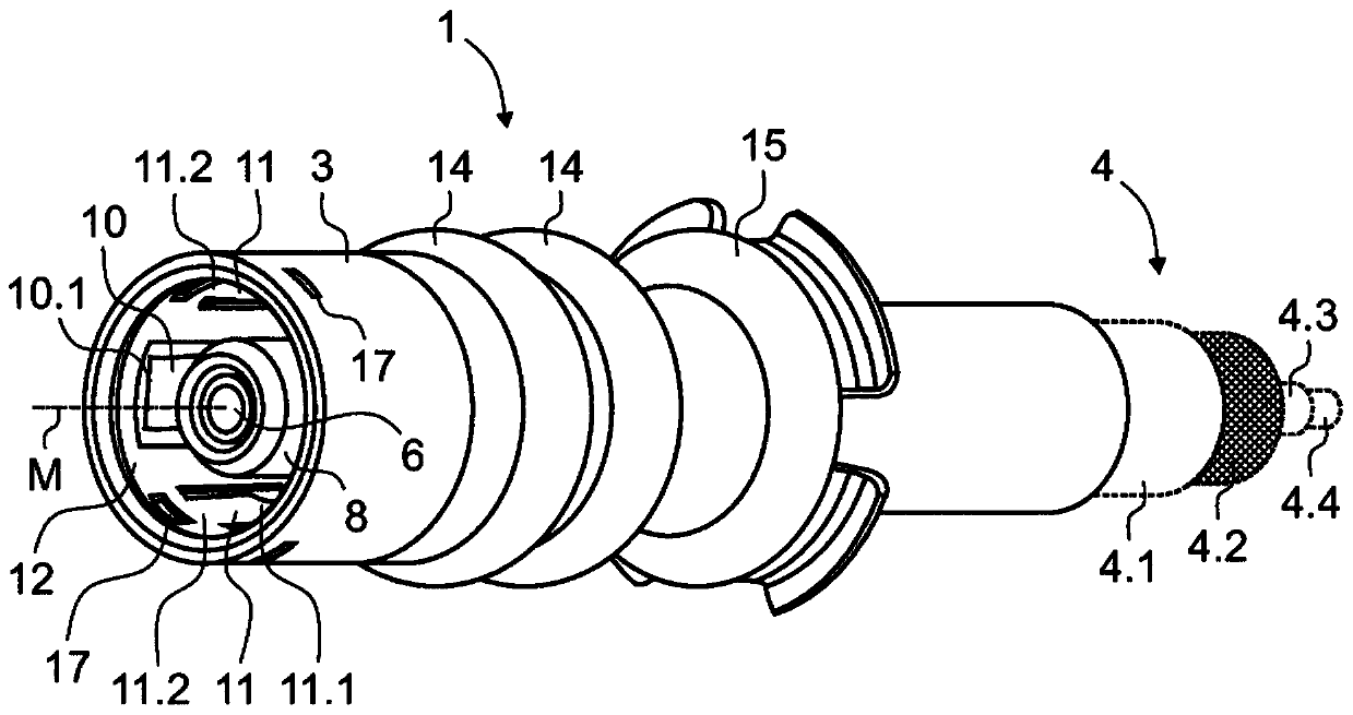
[0132] Figure 1 to Figure 6 Shown is a contact element 1 according to the invention for a connector 2 with Figure 11 The example in . The contact element 1 comprises a substantially tubular housing 3 made of metal. The housing 3 of the contact element 1 as well as all other parts of the contact element 1 can preferably be produced by stamping and bending techniques.

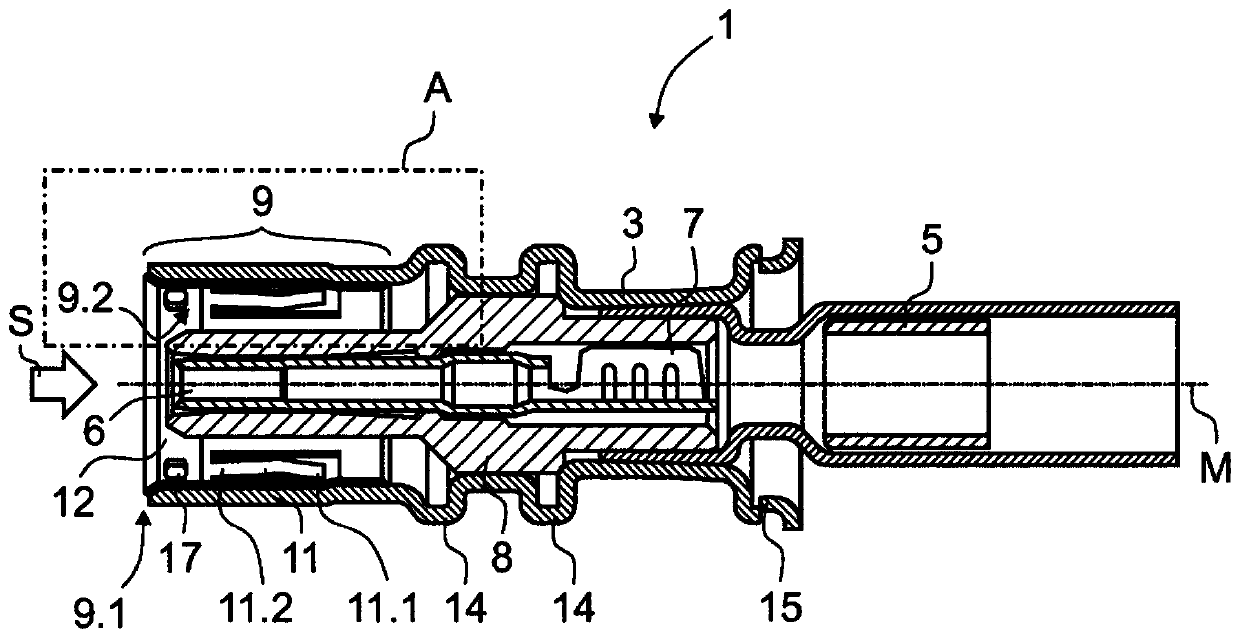
[0133] The housing 3 of the contact element 1 is designed for connection to the outer conductor 4.2 of a cable 4, in the present case a coaxial cable 4 (see figure 1 ). In this case the outer conductor 4.2 runs inside the insulating cable sheath 4.1. The dielectric 4.3 electrically isolates the outer conductor 4.2 from the inner conductor 4.4.

[0134] exist figure 2 and 6 The principle of connecting the contact element 1 to the coaxial cable 4 is particularly clearly shown in . The outer conductor 4.2 of the coaxial cable 4 can be connected to the housing 3 in a mechanically and electrically stable ma...


PUM


Abstract

The invention relates to a contact element (1) for a connector (2) having an at least partially conductive housing (3) for connection to a grounding conductor ( 4.2), and at least one inner conductor part (6) for connection to at least one signal lead (4.4) of the cable (4). In the insertion direction of the housing (3) in the front contact area (9) there are at least two elastic tongues (10, 11), wherein each elastic tongue (10, 11) is fixed in The first free end (10.1, 11.1) is movable and the second end (10.2, 11.2) is not movable. There are two sets of elastic tongues (10, 11), wherein the first set of elastic tongues (10) is arranged with its free end (10.1) facing the front end (9.1) of the contact area (9), the second set of elastic tongues The free end (11.1) of the shape (11) faces away from the front end (9.1) of the contact area (9).

Description

technical field [0001] The invention relates to a contact element for a connector having an at least partially conductive housing for connection to an outer conductor of an electric wire and having at least one inner conductor part for contact with at least one inner conductor of the electric wire Connection, as according to the preamble of claim 1. [0002] The invention also relates to a connector, in particular a coupling or bushing. Furthermore, the invention relates to a plug connection having a first connector, in particular a coupling or a bushing, and a second connector which can be inserted therein. Furthermore, it relates to a method for producing an electrical connection between two connectors according to the preamble of claim 15 . Background technique [0003] The connectors are used to establish electrical connections with corresponding other mating connectors. Connectors can be plugs, bushings, couplings or adapters. The term "connector" used in the contex...

Claims


Application Information

Patent Timeline
Patent Type & Authority Applications(China)
IPC IPC(8): H01R24/38H01R13/6582H01R13/187
CPCH01R13/187H01R13/6582H01R24/38H01R13/11
Inventor T·布雷德贝克M·泽布豪泽F·霍恩纳德
Owner ROSENBERGER HOCHFREQUENZTECHNIK GMBH & CO KG
Why Eureka
Try Eureka