A mixing tank locking mechanism, automatic locking system and automatic mixing system
A locking mechanism and automatic locking technology, which is applied to mixers, mixers with rotating containers, mixer accessories, etc., can solve problems such as laborious and laborious, throwing out of mixing barrels, loose pressure plates, etc., and avoid high failure rates , Reduce the risk of production accidents, and prevent production accidents
- Summary
- Abstract
- Description
- Claims
- Application Information
AI Technical Summary
Problems solved by technology
Method used
Image
Examples
Embodiment 1
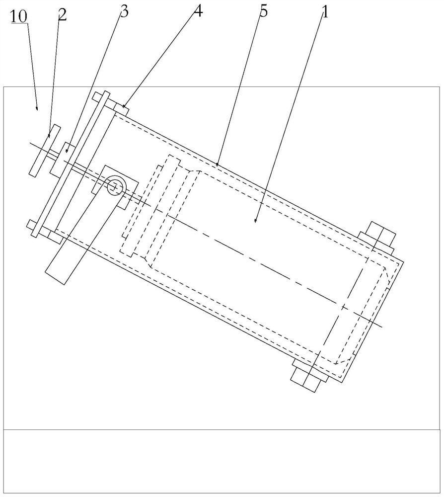
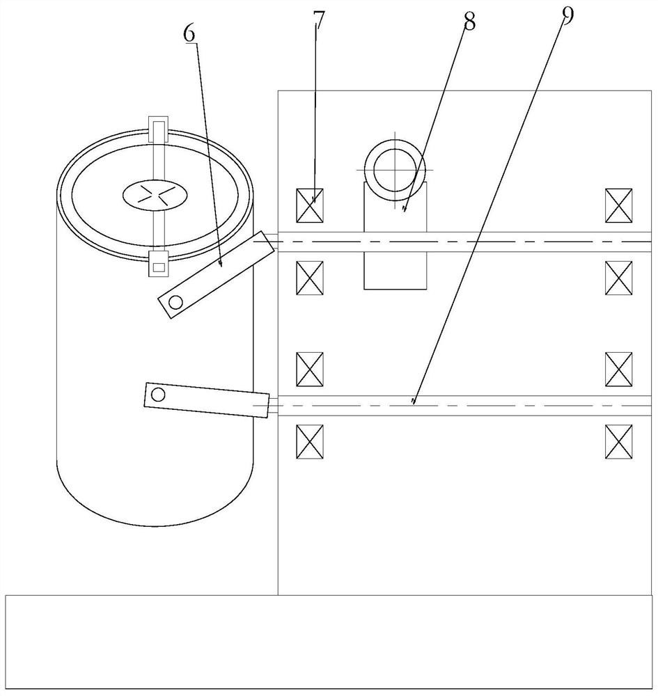
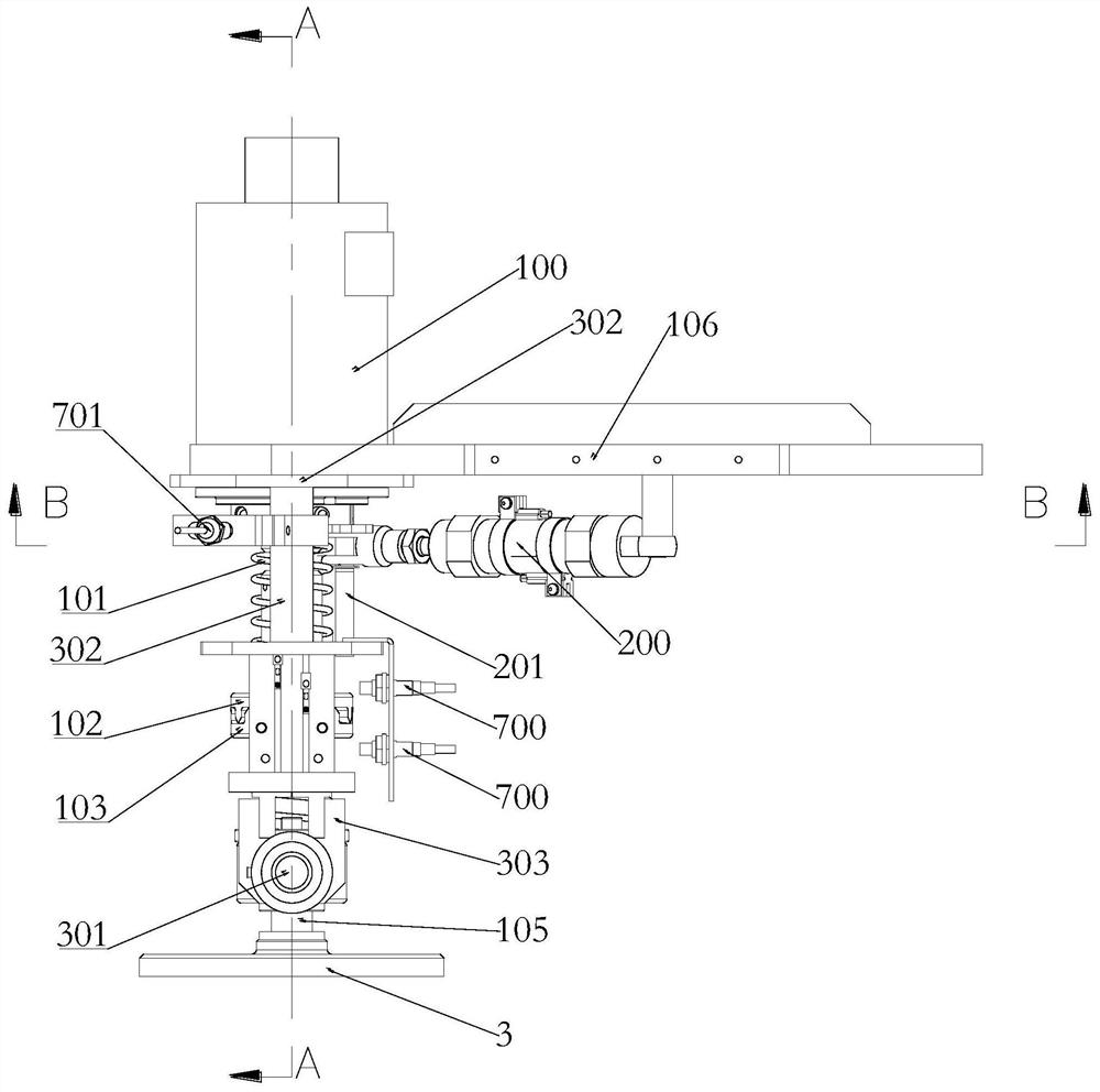
[0047] Such as Figure 3-Figure 12 As shown, a mixing tank locking mechanism of this embodiment is used to lock the mixing tank 1 in the mixing frame 5; it includes a driving device 100, a driving device 200, a clamping device 300, a lock Locking pin shaft 301 and locking screw rod 105, the clamping device 300 is used to clamp or release the locking pin shaft 301, the locking screw rod 105 passes through and is threadedly connected to the locking pin shaft 301 , the driving device 100 is installed on the clamping device 300 and drives the locking screw 105 to retract or extend from the locking pin 301; wherein, the driving device 2 200 drives the The clamping device 300 moves and the locking pin 301 is snapped into or out of the mixing frame 5, and when the driving device 100 drives the locking screw 105 to stretch out and compress the mixing bucket 1, the The clamping device 300 releases the locking pin 301 .
[0048] In this embodiment, the driving device 1 and the driving...
Embodiment 2
[0061] Such as Figure 7-Figure 12As shown, an automatic locking system for a mixing tank in this embodiment provides an automatic system for the locking mechanism in Embodiment 1, including the locking mechanism, telescopic sensor 700, and rotation detection sensor 701 and a PLC controller, the telescopic sensor 700 and the rotation detection sensor 701 are installed on the clamping device 300 respectively, and the telescopic sensor 700 and the rotation detection sensor 701 are used to respectively collect the The position information and rotation information of the drive shaft 104 are sent to the PLC controller, and the PLC controller is used to control the clamping device when the drive shaft 104 stops rotating and the drive shaft 104 reaches a preset position 300 to release the locking pin 301 .
[0062] A specific scheme of this embodiment is, as Figure 5 As shown, the drive shaft 104 is sleeved with a detection ratchet 702 that rotates synchronously with it, and the d...
Embodiment 3
[0065] Such as Figure 7-Figure 12 As shown, an automatic mixing system for a mixing tank in this embodiment includes the automatic locking system, and also includes a driving device 4800, an origin sensor 801, a mixing frame 5 and a photoelectric sensor. The origin sensor 801 It is used to collect the position information of the mixing frame 5 and send it to the PLC controller, and the PLC controller is used to control the driving end extension of the driving device 4800 when the mixing frame 5 is at the origin position. Entering into the mixing frame 5 provides support for the mixing bucket 1 to be put into the mixing frame 5 . It also includes lifting cylinder 2 802, articulated arm 803 and articulated seat 804, the lift cylinder 2 802 and articulated arm 803 are respectively hinged on the articulated seat 804, and the driving device 4 800 is installed on the articulated arm 803, The driving end of the lift cylinder 2 802 is hinged to the articulated arm 803 and drives the...
PUM
 Abstract
Description
Claims
Application Information
 - R&D
- Intellectual Property
- Life Sciences
- Materials
- Tech Scout
- Unparalleled Data Quality
- Higher Quality Content
- 60% Fewer Hallucinations
Browse by: Latest US Patents, China's latest patents, Technical Efficacy Thesaurus, Application Domain, Technology Topic, Popular Technical Reports.
© 2025 PatSnap. All rights reserved.Legal|Privacy policy|Modern Slavery Act Transparency Statement|Sitemap|About US| Contact US: help@patsnap.com


