
Workpiece paint spraying protection equipment adopting gliding flow guide principle

A technology for protecting equipment and workpieces, applied in spray booths, spraying devices, etc., can solve problems such as threats to life and health, achieve the effects of avoiding threats, preventing external diffusion from contacting workers, and improving absorption speed

Active Publication Date: 2019-12-20
WUHAN CHANGHENGRU ARTS & CRAFTS CO LTD
View PDF13 Cites 2 Cited by
  • Summary
  • Abstract
  • Description
  • Claims
  • Application Information

AI Technical Summary

Problems solved by technology

[0004] Aiming at the deficiencies in the prior art, the purpose of the present invention is to provide a workpiece painting protection device that adopts the principle of sliding drainage to solve the problem that although the prior art painting equipment has achieved good protection for the sealing of the painting process, workers have to When improving work efficiency, the workpiece will be taken out of the paint booth immediately after painting, causing the paint emitted in the air to be pumped out before it has completely settled, and has direct contact with the workers, causing a threat to life and health.

Method used


Image

  • Workpiece paint spraying protection equipment adopting gliding flow guide principle
  • Workpiece paint spraying protection equipment adopting gliding flow guide principle
  • Workpiece paint spraying protection equipment adopting gliding flow guide principle

Examples


Embodiment

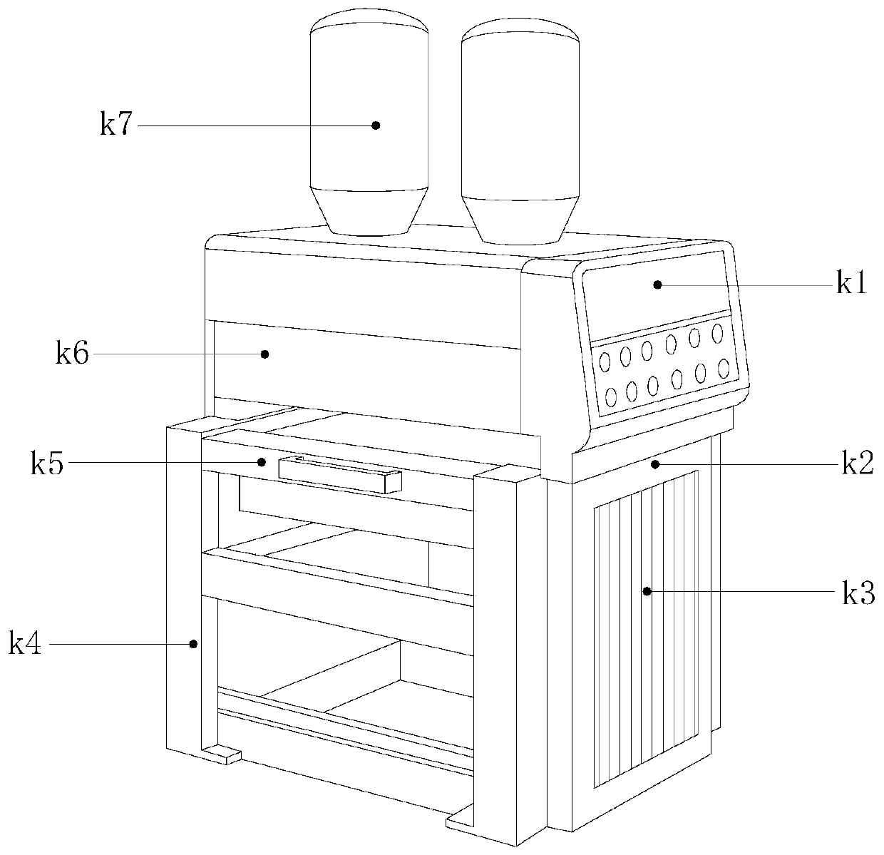
[0030] see Figure 1-Figure 7 , the present invention provides a kind of workpiece paint protection equipment that adopts the principle of sliding to drainage, and its structure includes controller k1, main machine k2, heat dissipation groove k3, fixed frame k4, support mechanism k5, paint spraying chamber k6, paint tank k7, described The host machine k2 has a rectangular structure, and is installed on the right end of the fixed frame k4 by embedding. The top of the fixed frame k4 is provided with a paint spraying chamber k6, and the left and right ends of the support mechanism k5 are fitted with the upper end of the fixed frame k4. Groove k3 is set in the middle of the host machine k2, and is an integrated structure. There are two paint tanks k7, which are installed on both ends of the top of the paint spraying chamber k6 by buckling, and the bottom of the paint spraying chamber k6 is connected to the support mechanism k5 connected, the bottom of the controller k1 is installe...


PUM


Abstract

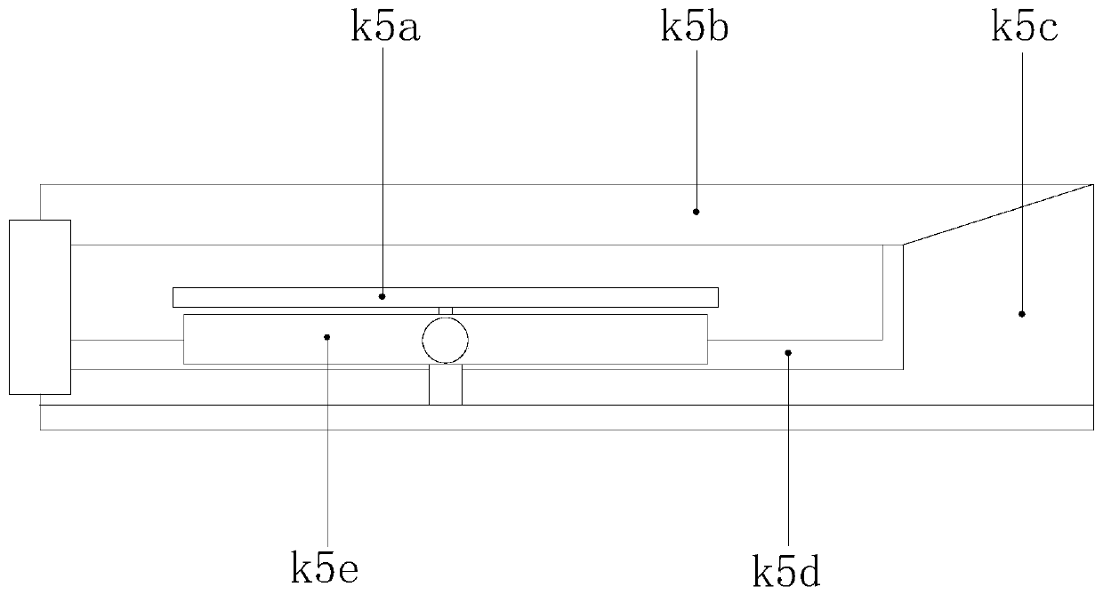
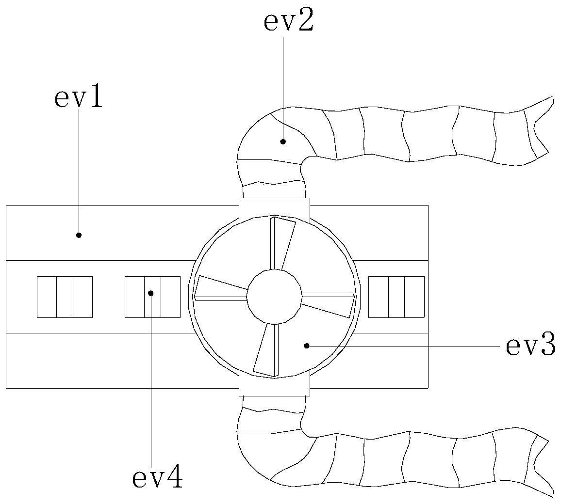
The invention discloses workpiece paint spraying protection equipment adopting a gliding flow guide principle. The structure of the workpiece paint spraying protection equipment adopting the gliding flow guide principle comprises a controller, a main machine, a cooling groove, a fixing frame, a piece supporting mechanism, a paint spraying bin and pigment tanks. The main machine is of a rectangularstructure and installed at the right end of the fixing frame in an embedded manner. The top end of the fixing frame is provided with the paint spraying bin. According to the workpiece paint sprayingprotection equipment adopting the gliding flow guide principle, in the process of pulling out the workpiece supporting mechanism, the top of the workpiece supporting mechanism drives a pressurizing mechanism to conduct air pressure control in a sealed bin, so that the harmful gas suction speed of a flow guide assembly is increased, the bottom of the workpiece supporting mechanism drives a suctionmechanism in the flow guide assembly to synchronously move, the bottom of the suction mechanism generates rotation in the process of cooperating with inclined-face top seats, harmful gas is sucked through a reverse fan, and the harmful gas is discharged through two exhaust cylinders finally; and in this way, it is ensured that internal harmful gas is rapidly sucked within the process of pulling out the workpiece supporting mechanism, it is avoided that the harmful gas spreads outward and makes contact with workers, and threat to the life health is avoided.

Description

technical field [0001] The invention relates to the field of painting processing of hardware parts, in particular to a workpiece painting protection device adopting the principle of sliding drainage. Background technique [0002] After the hardware is processed by the processing equipment, the surface needs to be painted. The traditional manual painting cannot meet the uniformity and yield requirements of the hardware surface. Therefore, it is necessary to use intelligent equipment for processing. Due to the high price of fully automated painting equipment, In order to reduce manufacturing costs, many manufacturers of hardware painting processing will purchase semi-automatic painting equipment, and use workers to load and replace materials. There are such problems in the use of existing technologies on the market: [0003] Although the paint spraying equipment of the prior art has achieved good protection for the sealing of the paint spraying process, in order to improve wo...

Claims


Application Information

Patent Timeline
IPC IPC(8): B05B16/00B05B14/40B05B13/02
CPCB05B13/0221B05B14/40B05B16/00
Inventor 谢丽阳
Owner WUHAN CHANGHENGRU ARTS & CRAFTS CO LTD
Learn More