A metal bar cutting machine

A technology of metal rods and cutting machines, which is applied in the direction of metal processing machinery parts, metal processing, metal processing equipment, etc., can solve the problems of frequent feeding frequency, etc., and achieve the effects of reducing labor costs, improving efficiency, and improving cutting efficiency

Active Publication Date: 2020-12-01
慈溪市家捷消防阀门有限公司
View PDF1 Cites 2 Cited by
  • Summary
  • Abstract
  • Description
  • Claims
  • Application Information

AI Technical Summary

Problems solved by technology

[0004] However, the operator has and can only install one copper rod into the feeding mechanism of the copper rod cutting machine. After the copper rod is cut, the next copper rod needs to be manually added, and the feeding frequency is frequent.

Method used


Image

  • A metal bar cutting machine
  • A metal bar cutting machine
  • A metal bar cutting machine

Examples


Embodiment Construction

[0046] The present invention will be described in further detail below in conjunction with the accompanying drawings.

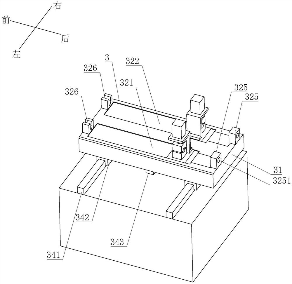
[0047] See attached figure 1 , a metal bar cutting machine mainly includes a frame, a cutting device 2, a feeding device 3 and a feeding device 4. Wherein, the feeding device 3 is located on one side of the cutting device 2 , and the feeding device 4 is located on the side of the feeding device 3 away from the cutting device 2 .

[0048] The frame has a lifting mechanism 11 for vertically lifting the cutting device 2 , a first installation platform 12 for installing the feeding device 3 and a second installation platform 13 for installing the feeding device 4 .

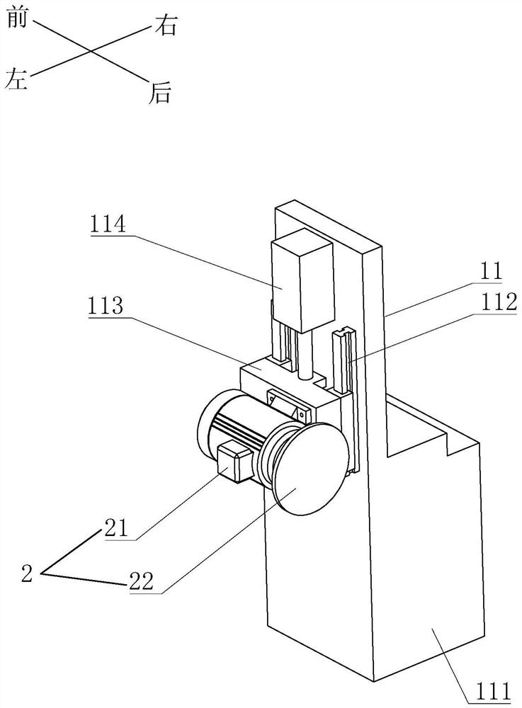
[0049] See attached figure 2 The elevating mechanism 11 includes a vertically arranged stand 111, an elevating slide rail 112 installed on the side of the stand 111 and vertically arranged, an elevating slide block 113 matched with the elevating slide rail 112 and driving the elevating slide block...


PUM


Abstract

The invention discloses a metal bar cutting machine which solves the problem that a metal bar cutting machine at the present stage feeds materials manually and consumes labor. According to the key points of the technical scheme, the metal bar cutting machine comprises a rack, a cutting device, a conveying device and a feeding device. The conveying device comprises a conveying platform, a first conveying mechanism, a second conveying mechanism and a first horizontal moving assembly. The feeding device comprises a feeding platform, a pushing mechanism, a supply table and a second horizontal moving assembly. The feeding platform is provided with a feeding slide groove for arranging metal bars in the front and back direction. The pushing mechanism can push the metal bars in the feeding slide groove into the conveying device. The supply table can transfer the metal bars into the feeding slide groove of the feeding platform one by one. The second horizontal moving assembly drives the feedingplatform to slide left and right. According to the metal bar cutting machine, operating workers do not need to add the metal bars one by one, and the automation degree of the metal bar cutting machine is improved.

Description

technical field [0001] The invention relates to a cutting device, in particular to a metal bar material cutting machine. Background technique [0002] In the production process of metal valves, a cutting machine is usually used to cut long metal bars into short metal segments, so as to facilitate subsequent melting and die-casting of the metal segments. [0003] The invention with authorized notification number CN208214445U discloses an intelligent and efficient copper rod cutting machine, including a machine base, a feeding table, a feeding mechanism with a combination of a driving seat and an adjustable pressure wheel seat, an adjustable positioning seat, and a and the cutting device between the driving seat and the swing device that drives the cutting device to swing up and down. [0004] But the operator has and can only install one copper rod in the feeding mechanism of the copper rod cutting machine. After the copper rod is cut, the next copper rod needs to be manuall...

Claims


Application Information

Patent Timeline
Patent Type & Authority Patents(China)
IPC IPC(8): B23D79/00B23Q7/00B23Q5/34B23Q3/08
CPCB23D79/00B23Q3/064B23Q3/08B23Q5/34B23Q7/00B23Q2703/04
Inventor 鄢洪运
Owner 慈溪市家捷消防阀门有限公司
Why Eureka
Try Eureka