Planetary reducer shell machining process and drilling mechanism

A planetary reducer and drilling mechanism technology, applied in the field of workpiece processing, can solve the problems of inconvenient recycling operation, increased labor intensity of workers, waste of resources, etc., and achieve the effects of convenient operation, high degree of automation, and resource saving

Active Publication Date: 2019-12-20
临安英明机械配件有限公司
View PDF5 Cites 5 Cited by
  • Summary
  • Abstract
  • Description
  • Claims
  • Application Information

AI Technical Summary

Problems solved by technology

[0004] However, during the drilling process, it is necessary to continuously spray water or coolant to the drill bit. If this part of water or coolant is not recycled, it will cause a great waste of resources; if this part of water or coolant is recycled, It is also necessary to filter out the workpiece waste in the water body or coolant before it can be reused. The recycling operation is inconvenient and increases the labor intensity of the workers, so it needs to be improved.

Method used


Image

  • Planetary reducer shell machining process and drilling mechanism
  • Planetary reducer shell machining process and drilling mechanism
  • Planetary reducer shell machining process and drilling mechanism

Examples


Embodiment 1

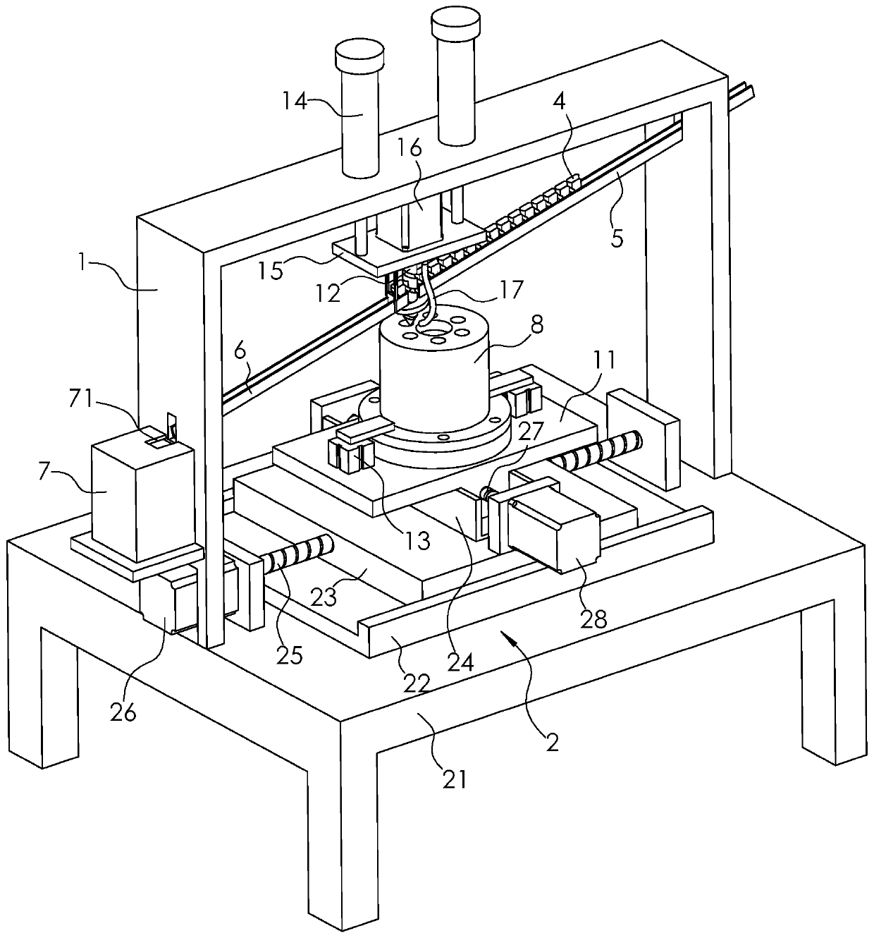
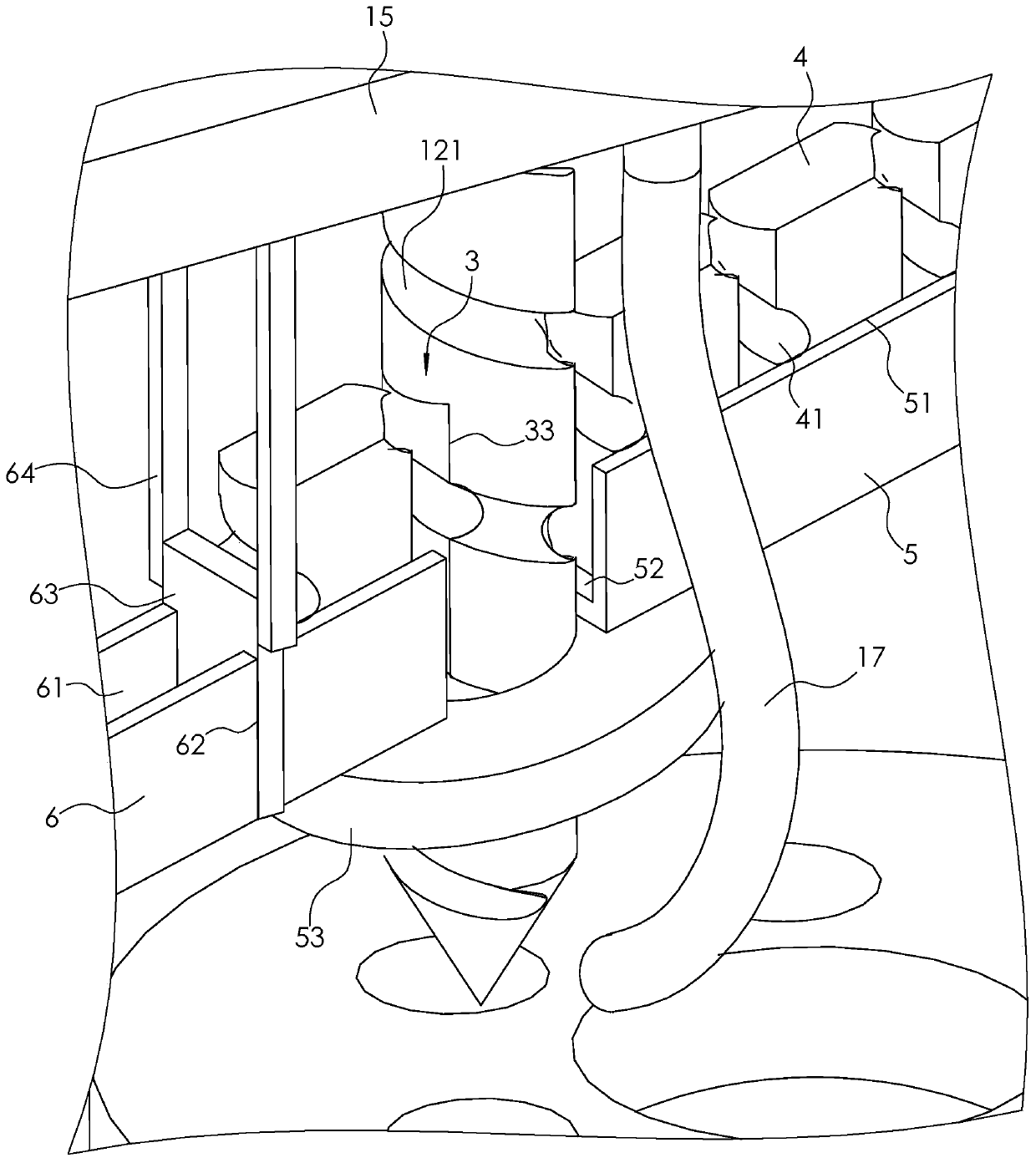
[0041] Embodiment one: if figure 2Shown, a kind of drilling mechanism comprises frame 1, and frame 1 is provided with workbench 11 and the drill bit 12 that is positioned at the top of workbench 11, and workbench 11 is provided with the fixture 13 that is used for clamping workpiece, and the workman can according to For different workpieces, corresponding fixtures 13 are selected to clamp the workpieces, so details will not be repeated here.

[0042] Such as figure 2 As shown, the frame 1 is also provided with a drive assembly 2, the drive assembly 2 includes a fixed plate 21 fixed on the frame 1, the fixed plate 21 is fixed with a first track 22 extending in the horizontal direction, the first track 22 is "U" shape setting; the first track 22 is slidingly embedded with a slide plate 23, the second track 24 is fixed on the slide plate 23, and the second slide track 6 is set in a "U" shape, and the extending direction of the second track 24 is in line with the first The ext...

Embodiment 2

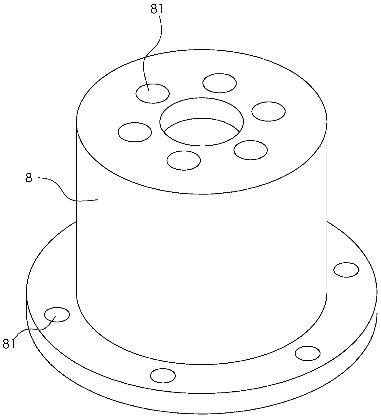
[0057] Embodiment 2: A processing technology for a planetary reducer housing 8, including the following steps:

[0058] A. Carry out rough grinding on the inner side of the planetary reducer housing 8 by a lathe;

[0059] B. Carry out rough grinding on the outer side of the planetary reducer housing 8 by a lathe;

[0060] C. Electrophoresis is performed on the planetary reducer housing 8 through the electrophoresis equipment. Since the electrophoresis equipment is a prior art, it will not be repeated here;

[0061] D. Carry out turning and fine grinding on the inner side of the planetary reducer housing 8 by a lathe;

[0062] E. Carry out turning and fine grinding on the outer side of the planetary reducer housing 8 by a lathe;

[0063] F, drill the top of the planetary reducer housing 8 through the drilling mechanism in Embodiment 1;

[0064] G. The bottom of the planetary reducer housing 8 is drilled through the drilling mechanism in Embodiment 1;

[0065] H. Use a tappi...


PUM


Abstract

The invention relates to the technical field of workpiece machining, especially relates to a planetary reducer shell machining process and a drilling mechanism. The process comprises a rack, the rackis provided with a working table, a driving component, a mounting plate, a drill bit, a driving part and a lifting part, the working table is provided with a clamp, the mounting plate is provided witha blowing device, the drill bit is provided with a through groove, the through groove comprises a groove body, a first notch and a second notch, the first notch is arranged at the first sliding rail,a plurality of heat conducting box and a driving piece, the first sliding rail is provided with a first sliding cavity and a limiting piece, the second groove is arranged at the mouth of the containing piece, the heat conducting boxes are filled with cooling mediums, the cooling mediums will rapidly cooling the drill bit, the driving piece and the containing piece realizes the heat conduction boxthe automatic material, and heat conduction box may be re-cooled so that the repeated utilization. The process ensures the cooling effect of the drill bit, saves resources, reduces the labor intensity of workers.

Description

technical field [0001] The invention relates to the technical field of workpiece processing, in particular to a processing technology and a drilling mechanism for a planetary reducer housing. Background technique [0002] The principle of the planetary reducer is a power transmission mechanism that uses the speed converter of the gear to reduce the number of revolutions of the motor to the desired number of revolutions and obtain a larger torque mechanism. The casing of the planetary reducer often needs to be drilled during the processing, and the drilling is realized by the drilling mechanism. [0003] Such as figure 1 As shown, the existing planetary reducer casing includes a casing 8, and the top and bottom of the casing 8 are provided with a plurality of through holes 81 in the circumferential direction, and the through holes 81 are processed by a drilling mechanism. During the drilling process of the casing 8, it is usually necessary to spray water or coolant to the d...

Claims


Application Information

Patent Timeline
Patent Type & Authority Applications(China)
IPC IPC(8): B23P15/00B23B41/00B23Q5/22B23Q11/00B23Q11/10
CPCB23B41/00B23P15/00B23Q5/22B23Q11/005B23Q11/10
Inventor 朱长龙廖建新吴贞亮黄飞张博孙昌卿
Owner 临安英明机械配件有限公司
Why Eureka
Try Eureka