Automatic production line applied to machining of steel channel of forklift gantry

An automatic production line and forklift gantry technology, applied in the direction of manufacturing tools and other manufacturing equipment/tools, can solve the problems of difficult to guarantee processing quality, low production efficiency, waste of manpower and material resources, etc., to improve the efficiency of channel steel processing and welding Effect

Pending Publication Date: 2019-12-20
ANHUI HAOYUN MACHINERY
View PDF0 Cites 8 Cited by
  • Summary
  • Abstract
  • Description
  • Claims
  • Application Information

AI Technical Summary

Problems solved by technology

[0002] Forklift mast channel steel is divided into inner mast channel steel and outer mast channel steel. The cross-sectional shape of the channel steel is U-shaped. On the two mutually perpendicular surfaces of the U-shape, there are surfaces that need to be processed. A roller shaft also needs to be welded on the steel. Before each gantry channel steel is welded with the roller shaft to form a welded part, its manufacturing process needs to go through three processes to complete. The process turnover of intermediate parts and transportation waste manpower and material resources; At the same time, the production efficiency is low, and the processing quality is difficult to guarantee

Method used


Image

  • Automatic production line applied to machining of steel channel of forklift gantry
  • Automatic production line applied to machining of steel channel of forklift gantry
  • Automatic production line applied to machining of steel channel of forklift gantry

Examples


Embodiment Construction

[0034] In the description of the present invention, unless otherwise specified, the orientation or positional relationship indicated by the terms "upper", "lower", "left", "right", "front", "rear", etc. are only for describing the present invention and simplifying the description, rather than Nothing indicating or implying that the referred device or structure must have a particular orientation should not be construed as limiting the invention. In addition, the terms "first", "second", etc. are used for descriptive purposes only, and should not be construed as indicating or implying relative importance.

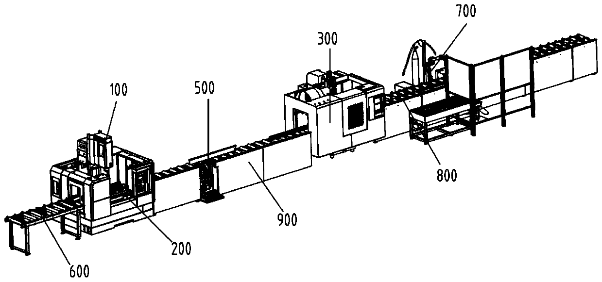
[0035] An automatic production line for processing channel steel of a forklift mast according to the present invention includes a first machining center, a first positioning mold, a second machining center, a second positioning mold, a channel steel turning center, a guide roller table, The roller shaft welding station and the clamping roller table, wherein the first machinin...


PUM


Abstract

The invention provides an automatic production line applied to machining of a steel channel of a forklift gantry. The automatic production line comprises a first machining center, a first positioningmold, a second machining center, a second positioning mold, a steel channel turnover center, a guide roller way, a rolling wheel shaft welding station and a clamping roller way, wherein the first machining center is used for forming screw holes in the steel channel which is in a vertical state; the first positioning mold is used for fixing the steel channel which is in the vertical state; the second machining center is used for forming screw holes in the steel channel which is in a horizontal state; the second positioning mold is used for fixing the steel channel in the horizontal state; the steel channel turnover center is used for switching the steel channel between the vertical state and the horizontal state; the guide roller way is used for conveying the steel channel to the first positioning mold; the rolling wheel shaft welding station is used for welding a rolling wheel shaft on the steel channel; and the clamping roller way is used for conveying the steel channel which is machined by the second machining center to the rolling wheel shaft welding station. By reasonably arranging the first machining center, the steel channel turnover center, the second machining center and the rolling wheel shaft welding station, the automatic production line provided by the invention implements four processes including formation of screw holes in the steel channel, turnover of the steelchannel, formation of screw holes in the steel channel and welding of the rolling wheel shaft, and improves the machining and welding efficiency of the steel channel.

Description

technical field [0001] The invention belongs to the technical field of channel steel processing, and in particular relates to an automatic production line for processing channel steel of forklift masts. Background technique [0002] Forklift mast channel steel is divided into inner mast channel steel and outer mast channel steel. The cross-sectional shape of the channel steel is U-shaped. On the two mutually perpendicular surfaces of the U-shape, there are surfaces that need to be processed. A roller shaft also needs to be welded on the steel. Before each gantry channel steel is welded with the roller shaft to form a welded part, its manufacturing process needs to go through three processes to complete. The process turnover of intermediate parts and transportation waste manpower and material resources; At the same time, the production efficiency is low, and the processing quality is difficult to guarantee. Contents of the invention [0003] The object of the present inven...

Claims


Application Information

Patent Timeline
Patent Type & Authority Applications(China)
IPC IPC(8): B23P23/06
CPCB23P23/06
Inventor 白献敏薛忠纯季王卫
Owner ANHUI HAOYUN MACHINERY
Why Eureka
Try Eureka