Wire withdrawing machine

A wire unwinding machine and wire unwinding technology, applied in the direction of conveying filamentous materials, thin material processing, transportation and packaging, etc., can solve the problems of many kinks, achieve affordable prices, improve product quality, and solve the effect of fiber winding

Pending Publication Date: 2019-12-20
HENGSHEN
View PDF0 Cites 0 Cited by
  • Summary
  • Abstract
  • Description
  • Claims
  • Application Information

AI Technical Summary

Problems solved by technology

[0003] The purpose of the present invention is to provide a wire unwinding machine, which can control the swing range of the fiber, solve the problem of more kinks in the traditional wire unwinding machine, and improve product quality

Method used


Image

  • Wire withdrawing machine
  • Wire withdrawing machine

Examples


Embodiment Construction

[0019] The present invention will be further described below in conjunction with the accompanying drawings. The following examples are only used to illustrate the technical solution of the present invention more clearly, but not to limit the protection scope of the present invention.

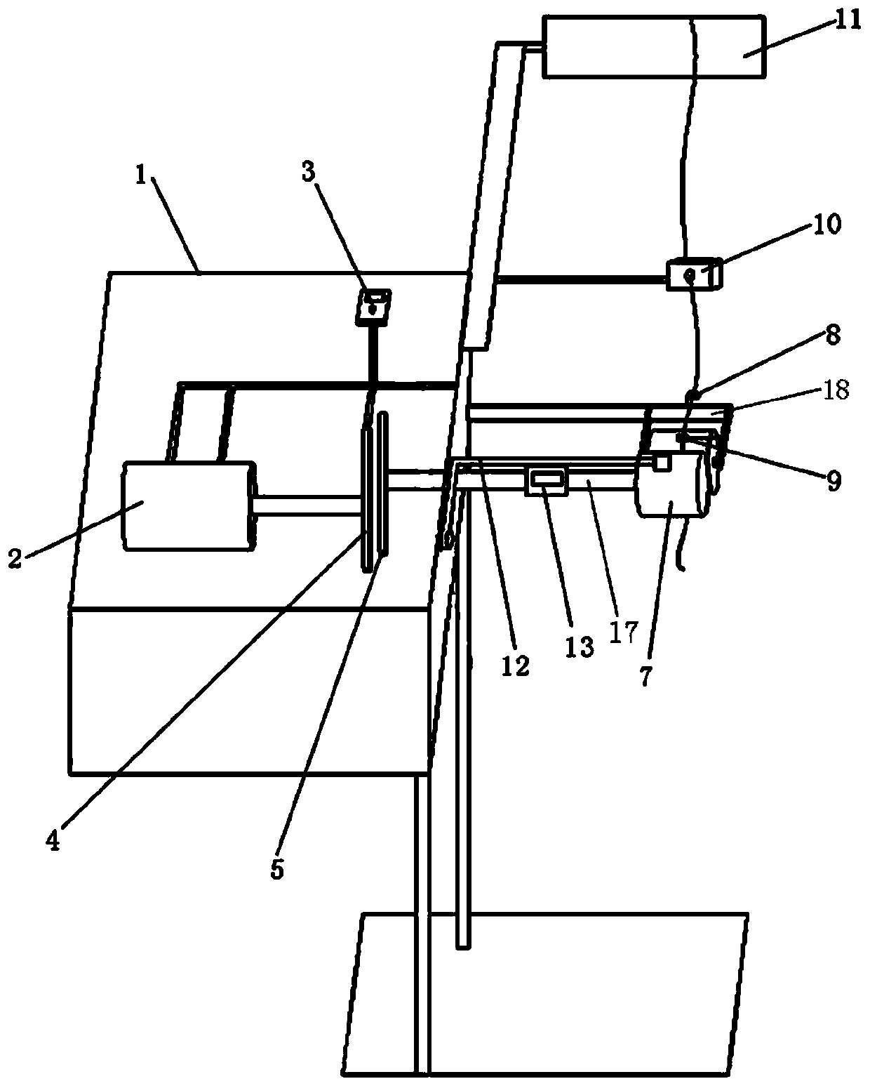
[0020] Such as figure 1 As shown, a wire unwinding machine includes a main frame 1 , a transmission device and an unwinding device arranged on the main frame 1 , and the transmission device is connected to the unwinding device through a rotating shaft 17 .

[0021] The transmission device includes a motor 2 , a speed controller 3 , a driving magnetic wheel 4 and a driven magnetic wheel 5 . The active magnetic wheel 4 is driven by the motor 2, and the driven magnetic wheel 5 is driven by the magnetic force between the active magnetic wheel 4 and the driven magnetic wheel 5. The staff holds a laser tachometer (produced by Guangzhou Suwei Electronic Technology Co., Ltd., model: SW-6234C) can dete...


PUM


Abstract

The invention discloses a wire withdrawing machine, and belongs to the technical field of mechanical equipment. The wire withdrawing machine comprises a transmission device and an unwinding device arranged on a main frame; the transmission device is connected with the unwinding device through a rotating shaft; the unwinding device comprises a guide roller set; the guide roller set comprises a first guide roller and a second guide roller; U type blocks are arranged on the two sides of the second guide roller, and are fixed on the main frame; springs and square blocks are arranged in grooves ofthe U type blocks; one ends of the springs are connected with the U type blocks, and the other ends are connected with square blocks; and the square blocks are connected with the end parts of a centershaft of the second guide roller. The wire withdrawing machine can control the fiber swing amplitude, solves the problem of more twists in a traditional wire withdrawing machine, and improves the product quality.

Description

technical field [0001] The invention relates to a wire unwinding machine, which belongs to the technical field of mechanical equipment. Background technique [0002] The unwinding device unwinds the fiber from the spindle through the guide roller for weft insertion movement of the loom. The unwinding process requires that the fibers are not wrapped around the rollers, and the unwound fibers are required to be flat and free of kinks. The traditional unwinding machine pulls the fiber directly from the spindle through the two guide rollers driven by the motor. It cannot control the left and right swing and twist of the fiber, and it is prone to fiber kink and roll entanglement, which will affect the quality of the fabric to a certain extent. Contents of the invention [0003] The purpose of the present invention is to provide an unwinding machine, which can control the swing range of the fiber, solve the problem of many kinks in the traditional unwinding machine, and improve...

Claims


Application Information

Patent Timeline
Patent Type & Authority Applications(China)
IPC IPC(8): B65H57/14B65H57/06B65H49/30B65H61/00B65H63/036B65H51/10B65H51/30
CPCB65H49/30B65H51/10B65H51/30B65H57/06B65H57/14B65H61/00B65H63/036B65H2701/31
Inventor 钱京燕春云王怡敏高志成刘婷
Owner HENGSHEN
Why Eureka
Try Eureka