Special U-shaped tube type heat exchanger tube box structure

A technology of heat exchanger tubes and U-shaped tubes, which is applied in the direction of heat exchanger types, indirect heat exchangers, fixed tubular conduit assemblies, etc., which can solve the problems of unbalanced force on tube sheets, increased equipment costs, and tube sheet heat exchange. Tube damage etc.

Pending Publication Date: 2019-12-20
HUALU ENG & TECH
View PDF0 Cites 0 Cited by
  • Summary
  • Abstract
  • Description
  • Claims
  • Application Information

AI Technical Summary

Problems solved by technology

If the temperature distribution of the tube sheet is uneven, it will lead to unbalanced stress on the tube sheet, and the simplified model in the calculation of the tube sheet will be quite different from the actual situation. Stress, which may lead to unexpected damage in tube sheets, tube boxes, and heat exchange tubes
[0004] With the increase of the operating temperature of the medium, the maximum stress that the material can withstand will continue to decrease. At this time, the equipment needs to increase the wall thickness to withstand the internal pressure, which not only increases the difficulty of equipment processing and manufacturing, but also increases the The cost of the equipment also reduces the reliability of the equipment. Therefore, how to make the U-shaped tube heat exchanger that handles high-temperature media work at a lower temperature, and at the same time balance the temperature distribution of the tube box and tube sheet is particularly important.

Method used


Image

  • Special U-shaped tube type heat exchanger tube box structure
  • Special U-shaped tube type heat exchanger tube box structure
  • Special U-shaped tube type heat exchanger tube box structure

Examples


Embodiment Construction

[0023] The content of the present invention will be further described below in conjunction with the accompanying drawings.

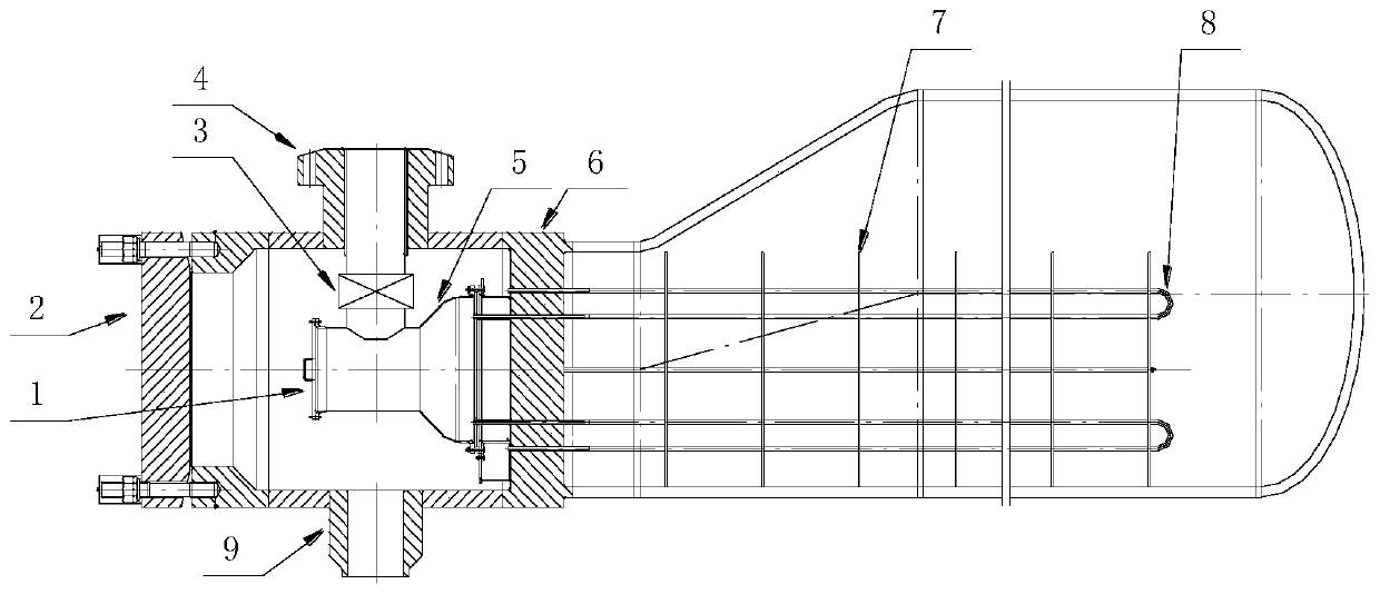
[0024] like figure 1 As shown, a special U-shaped tube heat exchanger tube box structure consists of three parts:

[0025] The first part is an independent cavity 5, which is composed of multi-section shells, directly connected to the heat fluid inlet pipe 4 of the tube box and the heat exchange tube 12 at the center of the tube sheet. The independent cavity 5 is provided with a displacement compensation device 3 to ensure that the independent cavity 5 Under extreme temperature difference, it will not be damaged due to excessive temperature difference stress. The high-temperature thermal fluid directly enters the independent cavity 5 from the thermal fluid inlet pipe 4 of the tube box, and the thermal fluid inlet tube 4 of the tube box is directly connected with the independent cavity 5 to ensure that the thermal fluid does not contact the casing 2 of t...


PUM


Abstract

The invention discloses a special U-shaped tube type heat exchanger tube box structure. Through the arrangement of the tube box with a hot fluid inlet of the independent cavity, using fountain type cloth tube, a cold fluid guide device and a special heat insulation structure, the thermal fluids directly into the center heat exchange tube and the tube plate, prevent the heated fluid in contact with the tube box shell, while the edge from the tube sheet of the heat exchange tube from the cooling fluid flow through the tube by the guiding device of the center heat exchange tube plate, finally enters a tube box, a tube box both cools the cooling housing, also the center heat exchange tube and the tube plate, and the purpose of reducing the U-shaped tube type heat exchanger tube pass design temperature, balance tube plate temperature distribution is achieved.

Description

technical field [0001] The invention relates to a tube box structure of a U-shaped tube heat exchanger. Background technique [0002] U-shaped tube heat exchanger is a kind of heat exchange equipment widely used in chemical industry, nuclear energy, metallurgy and other industries. The reason why this kind of equipment is widely used is that its tube bundle can be freely expanded and contracted, its structure is relatively simple, it will not produce temperature difference stress due to temperature difference of medium, and it has good reliability under high temperature and high pressure working conditions. [0003] Ordinary two-tube or multi-tube heat exchangers are often arranged from top to bottom or bottom to top between different tube passes, which causes the temperature of the tube sheet, tube box, and heat exchange tube to change in steps. It causes local high temperature or local low temperature in a certain area of ​​tube sheet, tube box and heat exchange tube. If...

Claims


Application Information

Patent Timeline
IPC IPC(8): F28D7/06
CPCF28D7/06
Inventor 刘家曦任超
Owner HUALU ENG & TECH
Why Eureka
Try Eureka