An all-fiber current transformer sensing device capable of active temperature compensation and a temperature compensation method

A technology of current transformer and temperature compensation, which is applied in the direction of measuring device, voltage/current isolation, measuring current/voltage, etc., can solve problems such as reduced service life, temperature drift of measurement accuracy, and difficult realization of algorithm structure, so as to avoid Reduced service life, strong resistance to temperature interference, and the effect of suppressing measurement errors

Active Publication Date: 2022-02-11
HARBIN UNIV OF SCI & TECH
View PDF9 Cites 0 Cited by
  • Summary
  • Abstract
  • Description
  • Claims
  • Application Information

AI Technical Summary

Problems solved by technology

[0003] The all-fiber current transformer uses sensing fiber to measure the current, and the sensing fiber is sensitive to the fluctuation of the operating environment temperature, which will cause the temperature drift of the measurement accuracy, and the sensing fiber is relatively fragile and operates at a lower temperature environment, will reduce its service life
[0004] In order to solve the temperature drift problem of the transformer, a temperature sensing optical fiber is usually used outside the shell of the signal processing unit to obtain the ambient temperature in real time and compensate the measurement error caused by the temperature through the corresponding algorithm, thereby improving the accuracy of the all-fiber current transformer temperature stability, a small part of the temperature sensor is built into the sensing ring, and relies on the temperature compensation algorithm to solve the problem of uneven heating of the sensing ring, but this kind of temperature compensation method is passive and depends heavily on the accuracy of the algorithm. The structure is complex and difficult to realize, the reliability is not high, and it cannot solve the impact of low temperature operation on the service life of the sensing fiber
[0005] To sum up, the existing all-fiber-optic current transformer temperature compensation technology uses compensation algorithms to solve the problem of temperature interference. This passive temperature compensation method has the problems of complexity and limited compensation capability. In addition, the existing temperature compensation technology is difficult Solve the problem that the service life of the sensing fiber is shortened when the sensing fiber is operated at a lower temperature, which greatly limits the application range of the all-fiber current transformer

Method used


Image

  • An all-fiber current transformer sensing device capable of active temperature compensation and a temperature compensation method
  • An all-fiber current transformer sensing device capable of active temperature compensation and a temperature compensation method
  • An all-fiber current transformer sensing device capable of active temperature compensation and a temperature compensation method

Examples


specific Embodiment approach 1

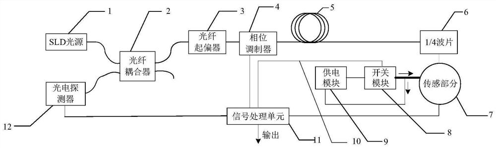
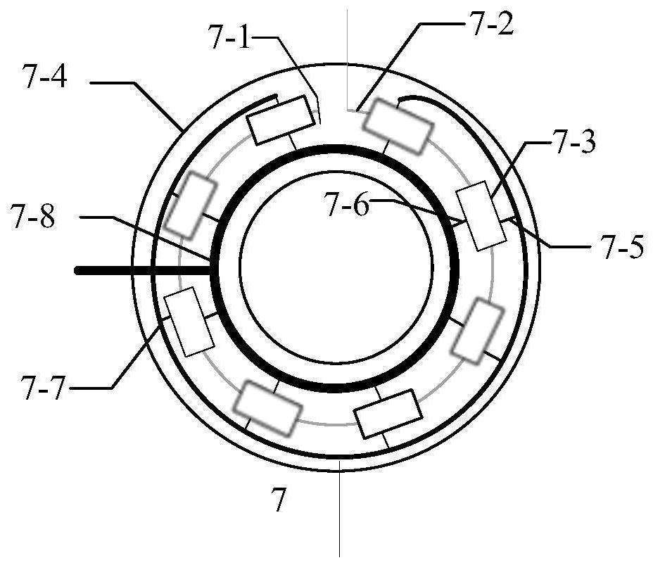
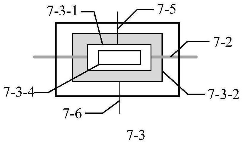
[0045] Specific implementation mode one: combine figure 1 , figure 2 , image 3 and Figure 4 To illustrate this embodiment: the scheme adopted by the present invention is: an all-fiber-optic current transformer sensing device capable of active temperature compensation, including an SLD light source 1, an optical fiber coupler 2, an optical fiber polarizer 3, and a phase modulator 4 , polarization maintaining optical fiber delay line 5, 1 / 4 wave plate 6, sensing part 7, switch module 8, power supply module 9, switch signal line 10, signal processing unit 11 and photodetector 12; Described sensing part comprises reflection Mirror 7-1, sensing optical fiber 7-2, N identical and equiangularly distributed temperature self-balancing heating devices 7-3, aluminum alloy shell 7-4, temperature sensor signal line 7-5, heater power line 7- 6. Sensing signal integration bus 7-7 and power line integration bus 7-8; the temperature self-balancing heating device 7-3 also includes a tempe...

specific Embodiment approach 2

[0061] Specific implementation mode two: combination figure 1 , figure 2 , Figure 5 and Figure 6 To illustrate this embodiment: the difference between this embodiment and the full fiber optic current transformer sensing device with active temperature compensation described in the first embodiment is that the heating device 7-3-2 in the temperature self-balancing device 7-3 It is composed of two heating solenoids with opposite winding directions, which generate two magnetic fields with the same magnitude and opposite directions. The effects of these two magnetic fields on the transformer can cancel each other out, preventing the interference generated by the heating solenoid 7-3-2 The magnetic field affects the measurement results of the all-fiber-optic current transformer, and the heating solenoid 7-3-2 is equidistantly placed on both sides of the temperature sensor 7-3-1, so that the measurement point where the temperature sensor 7-3-1 is located The temperature rise of...


PUM


Abstract

An all-optical current transformer sensing device capable of active temperature compensation and a temperature compensation method belong to the technical field of optical current sensing and measurement. The invention includes SLD light source, fiber coupler, fiber polarizer, switch module, power supply module, switch signal line, signal processing unit and photodetector; SLD light source and photodetector are connected with the input end of fiber coupler, and the fiber optic The polarizer is connected to the output end of the fiber coupler, the other end of the fiber polarizer is connected to the phase modulator, the phase modulator is connected to the polarization maintaining fiber delay line, and the polarization maintaining fiber delay line is connected to the 1 / 4 wave plate, 1 / 4 wave plate The other end of the power supply module is connected to the sensing part, one end of the power supply module is connected to the switch module, the switch module is connected to the sensing part, and the other end of the power supply module is connected to the sensing part; the signal processing unit is connected to the switch module through a switch signal line; the present invention can balance the sensing The temperature distribution of each point on the ring solves the problem of measurement error caused by uneven heating of the sensing ring.

Description

technical field [0001] The invention relates to an all-optical current transformer, in particular to an all-fiber current transformer sensing device capable of active temperature compensation, and belongs to the technical field of optical current sensing and measurement. Background technique [0002] With the development of the smart grid, the voltage level of the grid is getting higher and higher. The traditional electromagnetic current transformer can no longer meet the requirements of the modern smart grid due to various disadvantages such as magnetic circuit saturation, poor dynamic performance, and unsatisfactory insulation safety. system construction needs. With the development of modern optical fiber technology and digital electronic technology, it has become an inevitable trend for all-fiber current transformers to replace traditional electromagnetic current transformers. [0003] The all-fiber current transformer uses sensing fiber to measure the current, and the s...

Claims


Application Information

Patent Timeline
Patent Type & Authority Patents(China)
IPC IPC(8): G01R15/24G01R19/32
CPCG01R15/241G01R19/32
Inventor 程嵩陈庆国宋春辉林林
Owner HARBIN UNIV OF SCI & TECH
Why Eureka
Try Eureka