Optical receiver and optical communication device

A technology on the optical receiver and receiving side, which is applied in electromagnetic receivers, light guides, optics, etc., and can solve problems such as transmission distance limitations and easy degradation of optical waveforms

Active Publication Date: 2019-12-20
NIPPON SHEET GLASS CO LTD
View PDF14 Cites 0 Cited by
  • Summary
  • Abstract
  • Description
  • Claims
  • Application Information

AI Technical Summary

Problems solved by technology

If DMD occurs, the optical waveform will easily deteriorate, so the transmission distance may be limited

Method used


Image

  • Optical receiver and optical communication device
  • Optical receiver and optical communication device
  • Optical receiver and optical communication device

Examples


Embodiment Construction

[0033] The embodiments of the present invention will be described below. The same or equivalent constituent elements, members, and processes shown in the respective drawings are denoted by the same reference numerals, and repeated descriptions are appropriately omitted. In addition, the embodiment does not limit the invention but is only an example, and all the features or combinations described in the embodiment are not necessarily the essential content of the invention.

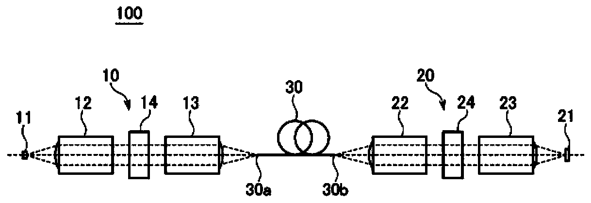
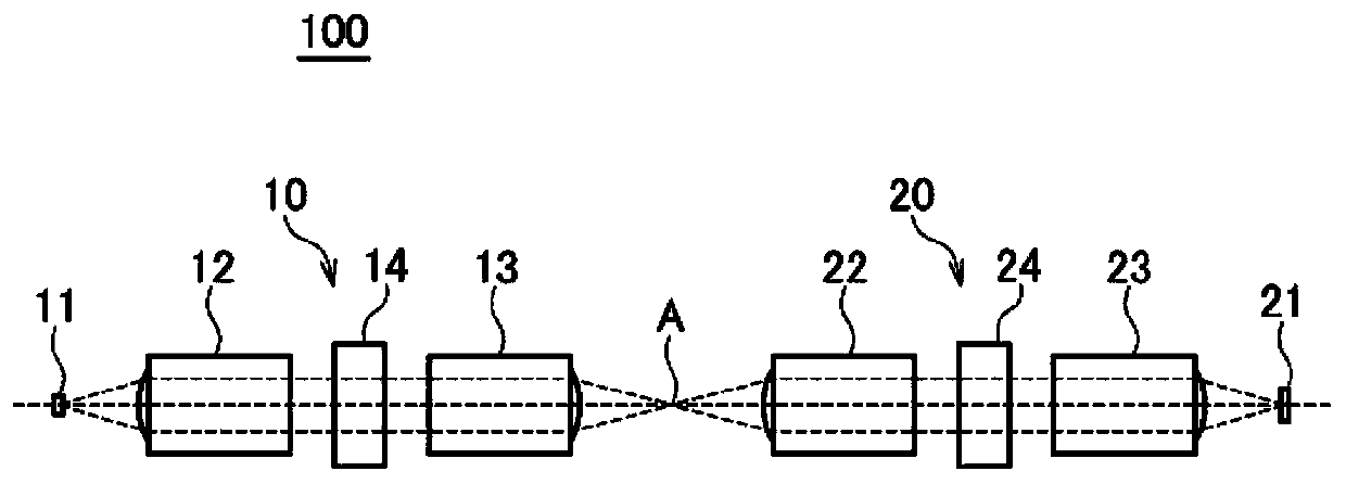
[0034] figure 1 It is a schematic diagram for explaining the optical communication device 100 according to the embodiment of the present invention. Such as figure 1 As shown, the optical communication device 100 includes: an optical transmitter 10, an optical receiver 20, and a multimode optical fiber 30 connected to the optical transmitter 10 and the optical receiver 20. The light beam transmitted from the optical transmitter 10 propagates in the multimode optical fiber 30 and is received by the optical rece...


PUM


Abstract

This optical receiver (20) receives, with a light-receiving element (21), a light beam having a spiral wave surface propagated through a multimode fiber (30). The optical receiver (20) is provided with a receiving side vortex optical element (24) disposed between the multimode fiber (30) and the light-receiving element (21).

Description

Technical field [0001] The invention relates to an optical receiver and an optical communication device. Background technique [0002] In recent years, with the popularization of the Internet and cloud computing, the amount of data communication has increased explosively. In a data center that temporarily stores data or is connected to the Internet, high-speed exchange of large-capacity data is also required. [0003] In the short-distance (tens of meters to hundreds of meters) transmission such as in a data center, communication is also performed by electrical signals, but optical communication is more advantageous in terms of high speed. In short-distance optical communications, a system that combines a surface-emitting light source such as a VCSEL (Vertical Cavity Surface Emitting LASER) with a multimode fiber and a transmission speed of several GHz to 10 GHz has been realized. [0004] Because the core of the multi-mode fiber through which the light passes is designed to be lar...

Claims


Application Information

Patent Timeline
Patent Type & Authority Applications(China)
IPC IPC(8): G02B6/26G02B6/43
CPCG02B6/26G02B6/43G02B6/4204G02B6/4206H04B10/2581H04B10/66
Inventor 常友启司日下哲
Owner NIPPON SHEET GLASS CO LTD
Why Eureka
Try Eureka