Vehicle body automatic brushing facility

An automatic and body technology, applied in vehicle cleaning equipment, vehicle cleaning, vehicle maintenance, etc., can solve the problems of insufficient cleaning, cost, and low efficiency, and achieve the effect of scrubbing clean and bright

Active Publication Date: 2019-12-24
车泊喜智能科技(山东)有限公司
View PDF5 Cites 4 Cited by
  • Summary
  • Abstract
  • Description
  • Claims
  • Application Information

AI Technical Summary

Problems solved by technology

[0005] In order to overcome the shortcomings of manually scrubbing the vehicle body, which is not only inefficient, but also requires more manpower, it is difficult to clean the pedals at a lower position in the prior art, or the cleaning is not clean enough. Therefore, the technology of the present invention The problem is: to provide an automatic car body scrubbing equipment that can fully scrub the body and pedals automatically, clean the pedals, and have high cleaning efficiency

Method used


Image

  • Vehicle body automatic brushing facility
  • Vehicle body automatic brushing facility
  • Vehicle body automatic brushing facility

Examples


Embodiment 1

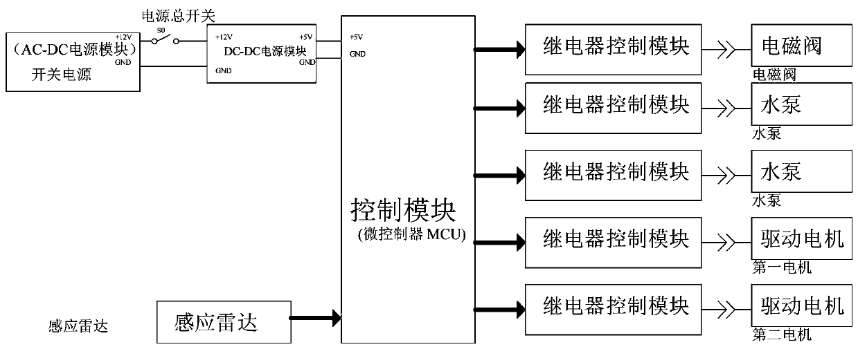
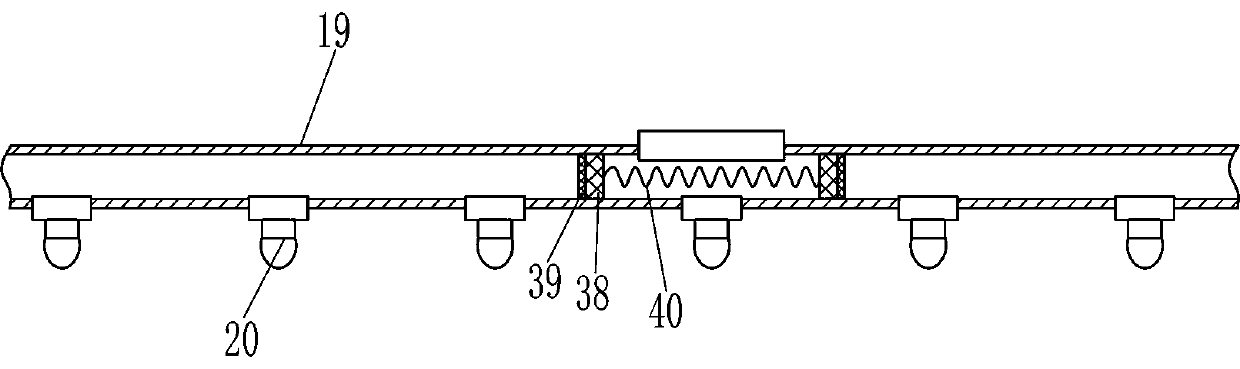
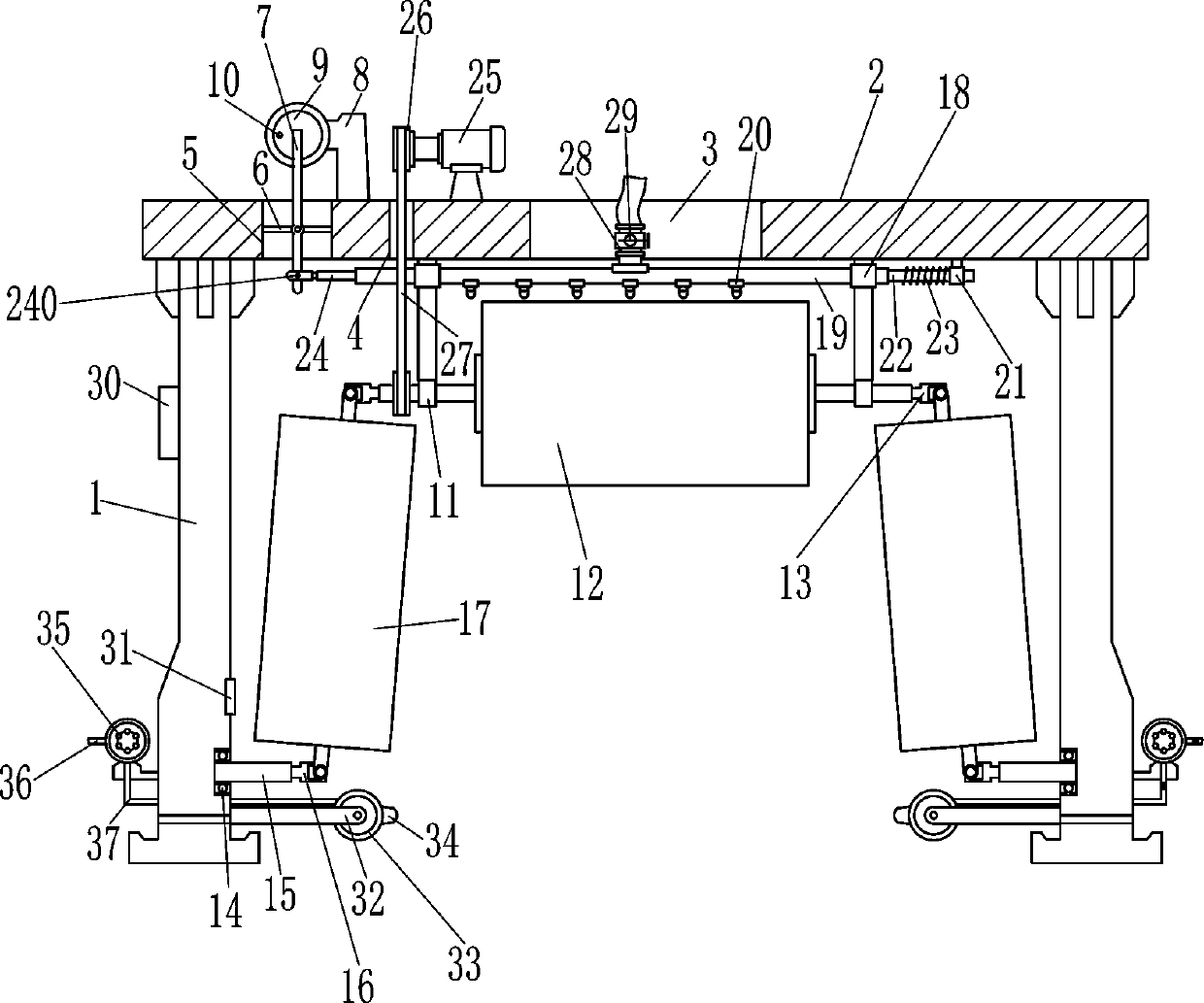
[0018] A car body automatic brushing equipment, such as Figure 1-4 As shown, it includes a support plate 1, a mounting plate 2, a first support rod 6, a first rotating rod 7, a first motor 8, a rotating disk 9, a push rod 10, a first bearing seat 11, a first brush cylinder 12, The first universal joint 13, the second bearing seat 14, the first rotating shaft 15, the second universal joint 16, the second brush tube 17, the first guide sleeve 18, the first hollow tube 19, the first nozzle 20, the first Two guide sleeves 21, moving rod 22, first compression spring 23, telescopic rod 24, second rotating rod 240, second motor 25, pulley 26, flat belt 27, first liquid inlet pipe 28, solenoid valve 29, control box 30 and induction radar 31, the left and right sides of the bottom of the mounting plate 2 are connected with the supporting plate 1, the mounting plate 2 is connected with the supporting plate 1 by welding, the middle part of the mounting plate 2 has a first opening 3, and...

Embodiment 2

[0020] A car body automatic brushing equipment, such as Figure 1-4As shown, it includes a support plate 1, a mounting plate 2, a first support rod 6, a first rotating rod 7, a first motor 8, a rotating disk 9, a push rod 10, a first bearing seat 11, a first brush cylinder 12, The first universal joint 13, the second bearing seat 14, the first rotating shaft 15, the second universal joint 16, the second brush tube 17, the first guide sleeve 18, the first hollow tube 19, the first nozzle 20, the first Two guide sleeves 21, moving rod 22, first compression spring 23, telescopic rod 24, second rotating rod 240, second motor 25, pulley 26, flat belt 27, first liquid inlet pipe 28, solenoid valve 29, control box 30 and induction radar 31, the left and right sides of the bottom of the mounting plate 2 are connected with the supporting plate 1, the middle part of the mounting plate 2 has a first opening 3, and the left part of the mounting plate 2 has a second opening 4 and a third o...

Embodiment 3

[0023] A car body automatic brushing equipment, such as Figure 1-4 As shown, it includes a support plate 1, a mounting plate 2, a first support rod 6, a first rotating rod 7, a first motor 8, a rotating disk 9, a push rod 10, a first bearing seat 11, a first brush cylinder 12, The first universal joint 13, the second bearing seat 14, the first rotating shaft 15, the second universal joint 16, the second brush tube 17, the first guide sleeve 18, the first hollow tube 19, the first nozzle 20, the first Two guide sleeves 21, moving rod 22, first compression spring 23, telescopic rod 24, second rotating rod 240, second motor 25, pulley 26, flat belt 27, first liquid inlet pipe 28, solenoid valve 29, control box 30 and induction radar 31, the left and right sides of the bottom of the mounting plate 2 are connected with the supporting plate 1, the middle part of the mounting plate 2 has a first opening 3, and the left part of the mounting plate 2 has a second opening 4 and a third ...


PUM


Abstract

The invention relates to a brushing facility, in particular to a vehicle body automatic brushing facility. Consequently, according to the technical problem, the vehicle body automatic brushing facility which can automatically and fully brush a vehicle body and a footrest, can clean the footrest and is high in cleaning efficiency is provided. According to the technical scheme, the vehicle body automatic brushing facility comprises supporting plates, an installation plate, a first supporting rod, a first rotating rod, a first motor, a rotary table, a push rod, first bearing pedestals, a first brush barrel and the like. The supporting plates are connected with the left side and the right side of the bottom of the installation plate. By the adoption of the vehicle body automatic brushing facility, the position of an automobile is detected by an induction radar, when the automobile runs through the right side of the induction radar, a control module can control the first motor, a second motor, a solenoid valve and water pumps to be started, and the first motor can drive a first hollow pipe to move left and right so that water can be sprayed out through first spray nozzles, and the spraying range can be broader; and the second motor drives the first brush barrel and second brush barrels to rotate, and therefore the vehicle body is fully brushed.

Description

technical field [0001] The invention relates to a scrubbing device, in particular to an automatic scrubbing device for a vehicle body. Background technique [0002] With the development of society, cars have become a means of transportation for people to travel. With the increase of cars, the air quality has also declined. There are often dust floating in the air. During the driving process of cars, dust will be attached to the surface of the body for a long time. After washing, the car body will become dirty and affect the appearance, and there may be corrosive liquid stuck on it, which will cause the paint surface of the car body to be damaged. For car pedals, people often step on them when getting on and off the car, and the position of the pedals will be higher than that of other cars. The place is dirtier, so people will scrub the car body after the car has been used for a period of time, so as to wash off the dust or foreign matter on the car body surface. [0003] Ge...

Claims


Application Information

Patent Timeline
Patent Type & Authority Applications(China)
IPC IPC(8): B60S3/06B60S3/04
CPCB60S3/06B60S3/066B60S3/04
Inventor 郭一帆
Owner 车泊喜智能科技(山东)有限公司
Why Eureka
Try Eureka