Hydraulic oil cylinder based on decompression and force reduction

A hydraulic cylinder and pressure relief technology, which is applied in the field of hydraulic cylinders based on pressure relief and force reduction, to achieve the effects of improving stability, simple and convenient installation, and improving safety

Active Publication Date: 2019-12-24
浙江拓邦液压科技有限公司
View PDF8 Cites 2 Cited by
  • Summary
  • Abstract
  • Description
  • Claims
  • Application Information

AI Technical Summary

Problems solved by technology

[0005] In view of the problems existing in the prior art, the object of the present invention is to provide a hydraulic cylinder based on pressure relief and force reduction, which can reduce the inertia between the piston and the hydraulic cylinder body when the piston moves to the maximum stroke by setting the pressure relief member The impact force makes the hydraulic cylinder body less likely to be damaged under the long-term impact of the piston, thereby improving the stability of the hydraulic system. At the same time, through the cooperation between the fastening frame and the arc-shaped limit plate, the movement After stopping at a certain position, the piston rod is positioned and clamped, so that when the hydraulic oil pipe is damaged or the cylinder seal is poor during the use of the hydraulic cylinder body, the piston rod is not easy to fall back, which improves the safety of the hydraulic cylinder body.

Method used


Image

  • Hydraulic oil cylinder based on decompression and force reduction
  • Hydraulic oil cylinder based on decompression and force reduction
  • Hydraulic oil cylinder based on decompression and force reduction

Examples


Embodiment 1

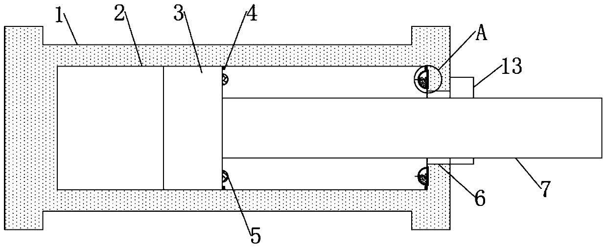
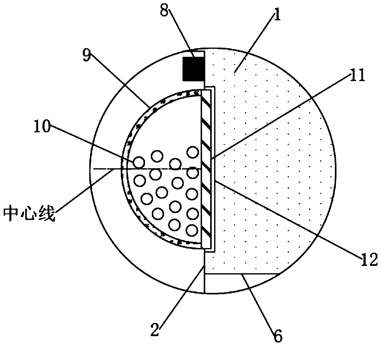
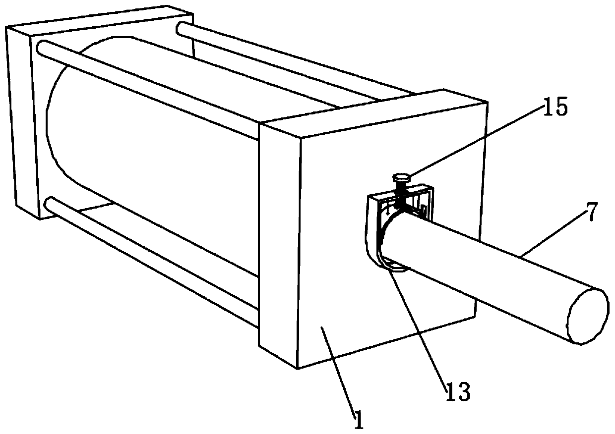
[0043] see figure 1 , a hydraulic cylinder based on pressure relief and force reduction, including a hydraulic cylinder body 1, an oil storage chamber 2 is excavated inside the hydraulic cylinder body 1, a telescopic port 6 is dug at the right end of the hydraulic cylinder body 1, and the telescopic port 6 is connected to the oil storage chamber 2 The piston 3 is slidingly connected to the oil storage chamber 2, the piston rod 7 is fixedly connected to the right end of the piston 3, the piston rod 7 is matched with the telescopic port 6, and the right end of the piston 3 is fixedly connected to two rubber raised hemispheres 5, two rubber The raised hemisphere 5 is symmetrical about the piston rod 7, the area of ​​the rubber raised hemisphere 5 is smaller than the area of ​​the rubber wrapped hemisphere 9, and the position of the centerline of the rubber raised hemisphere 5 and the position of the centerline of the rubber wrapped hemisphere 9 are located on the same horizontal p...


PUM


Abstract

The invention discloses a hydraulic oil cylinder based on decompression and force reduction, and belongs to the field of hydraulic equipment. The hydraulic oil cylinder based on decompression and force reduction comprises a hydraulic oil cylinder body, wherein an oil storage chamber is dug in the hydraulic oil cylinder body; a telescopic port is dug in the right end of the hydraulic oil cylinder body and communicates with an oil storage chamber; a piston is slidably connected into the oil storage chamber; through arranging a decompression piece, an inertia impact force between the piston and the hydraulic oil cylinder body when the piston moves to the maximum stroke can be reduced, so that the phenomenon that the hydraulic oil cylinder body is damaged under a long-time impact effect of thepiston is not easy to occur, and the working stability of a hydraulic system is further improved; and meanwhile, through the matched use between a fastening frame and an arc-shaped limiting plate, the piston rod stopped after moving to a certain position is positioned and clamped, so that when the phenomenon that a hydraulic oil pipe is damaged or the oil cylinder is poor in sealing performance in the use process of the hydraulic oil cylinder body occurs, the piston rod is not easy to fall back, and the use safety of the hydraulic oil cylinder body is improved.

Description

technical field [0001] The invention relates to the field of hydraulic equipment, in particular to a hydraulic oil cylinder based on pressure relief and force reduction. Background technique [0002] In the machinery industry, the hydraulic cylinder is an important part of power transmission, and the working environment is harsh, especially in the metallurgy, mining and shipping industries, which have high requirements for the operation of machinery and equipment. In the process of mechanical transmission, hydraulic cylinders In the harsh working environment of high pressure, impact and instability, hydraulic cylinders are widely used in the control process of industrial production. The hydraulic cylinder is the actuator in the hydraulic transmission system. It is an energy conversion device that converts hydraulic energy into mechanical energy. It is used to drive the working mechanism to perform linear reciprocating motion or reciprocating swing. Its transmission works smo...

Claims


Application Information

Patent Timeline
Patent Type & Authority Applications(China)
IPC IPC(8): F15B15/14F15B15/24
CPCF15B15/1423F15B15/1428F15B15/1447F15B15/1457F15B15/24
Inventor 陈金华
Owner 浙江拓邦液压科技有限公司
Why Eureka
Try Eureka