Firmware upgrading method and system of optical module and optical module

A firmware upgrade and optical module technology, applied in the field of optical communication, can solve problems such as short interruption of communication services and failure of optical module 10 to work normally, and achieve the effect of reducing possibility and interruption

Pending Publication Date: 2019-12-24
HISENSE BROADBAND MULTIMEDIA TECH
View PDF6 Cites 1 Cited by
  • Summary
  • Abstract
  • Description
  • Claims
  • Application Information

AI Technical Summary

Problems solved by technology

When the single-chip microcomputer runs the Bootloader program, the firmware stops running, so that the optical module 10 cannot work normally, resulting in a brief interruption of the communication service

Method used


Image

  • Firmware upgrading method and system of optical module and optical module
  • Firmware upgrading method and system of optical module and optical module
  • Firmware upgrading method and system of optical module and optical module

Examples


Embodiment 1

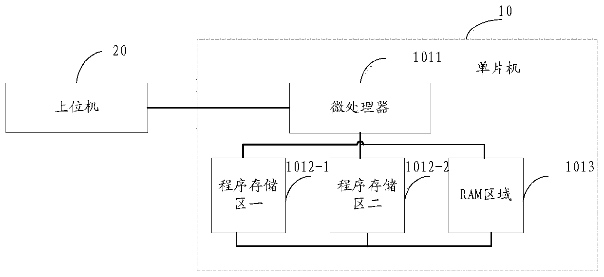
[0048] read on image 3 , when the optical module is started, the firmware code stored in program storage area 1012-1 is the firmware code of the latest version currently available, and the identification value corresponding to the corresponding program storage area 1012-1 is the first signature, and the program storage area 2 The firmware code stored in 1012-2 is an old version of the firmware code, and the identification value corresponding to the corresponding program storage area 2 1012-2 is the second signature.

[0049] When the optical module starts, the microprocessor 1011 determines that the program storage area 1012-1 is the first program area, and calls the firmware code stored in the program storage area 1012-1. The firmware code includes: initialization code and non-initialization code. The microprocessor 1011 first runs the initialization code to initialize the optical module, and then runs the non-initialization code. The microprocessor 1011 obtains the firmwa...

Embodiment 2

[0052] read on image 3, when the optical module is started, the firmware code stored in program storage area 1012-1 is the firmware code of the latest version currently available, and the identification value corresponding to the corresponding program storage area 1012-1 is the first signature, and the program storage area 2 The firmware code stored in 1012-2 is an old version of the firmware code, and the identification value corresponding to the corresponding program storage area 2 1012-2 is the second signature.

[0053] When the optical module starts, the microprocessor 1011 determines that the program storage area 1012-1 is the first program area, and calls the firmware code stored in the program storage area 1012-1. The firmware code includes: initialization code and non-initialization code. The microprocessor 1011 first runs the initialization code to initialize the optical module, and then runs the non-initialization code. The microprocessor 1011 obtains the firmwar...


PUM


Abstract

The embodiment of the invention discloses a firmware upgrading method and system of an optical module and the optical module. The optical module comprises a microprocessor and a program storage area connected with the microprocessor. When the optical module works normally, the microprocessor operates the firmware codes stored in a program storage area, and the firmware codes comprise the initialization codes and the non-initialization codes. The microprocessor firstly operates the initialization code to initialize the optical module, and then operates the non-initialization code, when an uppercomputer writes all firmware upgrading codes into the program storage area, the upper computer sends an upgrading completion notice to the microprocessor, and the microprocessor operates the upgrading non-initialization code in response to an upgrading completion notification sent by the upper computer, so that according to the technical scheme, after the firmware upgrading is completed, the microprocessor directly runs the upgrading non-initialization code, and the initialization process is not needed, and accordingly the situation that communication services are interrupted does not occur.

Description

technical field [0001] Embodiments of the present application relate to optical communication technologies. More specifically, it relates to a firmware upgrade method of an optical module, a system and an optical module. Background technique [0002] An optical transceiver integrated module, referred to as an optical module, is a standard module in equipment in the field of optical communication, used for photoelectric conversion. like figure 1 As shown, the optical module 10 is composed of an optical transmitter 102, an optical receiver 103, a single-chip microcomputer 101 and the like. Wherein, the single-chip microcomputer 101 of the optical module 10 controls the optical transmitter 102 to convert the electrical signal into an optical signal. The optical receiver 103 of the optical module 10 can receive the optical signal transmitted by the optical fiber, and convert the received optical signal into an electrical signal under the control of the single-chip microcomput...

Claims


Application Information

Patent Timeline
Patent Type & Authority Applications(China)
IPC IPC(8): G06F8/65
CPCG06F8/65
Inventor 王安忆李刚王麟
Owner HISENSE BROADBAND MULTIMEDIA TECH
Why Eureka
Try Eureka