Large computer power supply protection equipment

A large-scale computer, power supply protection technology, applied in computing, protection switches, emergency protection devices, etc., can solve problems such as computer damage

Active Publication Date: 2019-12-24
贵州云腾未来科技有限公司
View PDF11 Cites 2 Cited by
  • Summary
  • Abstract
  • Description
  • Claims
  • Application Information

AI Technical Summary

Problems solved by technology

[0002] The computer has become an indispensable item in people's life, and the computer also plays a vital role in the work, but due to the computer damage caused by the instability of the working voltage, in order to protect the computer, this large-scale Computer power supply protection equipment

Method used


Image

  • Large computer power supply protection equipment
  • Large computer power supply protection equipment
  • Large computer power supply protection equipment

Examples


specific Embodiment approach 1

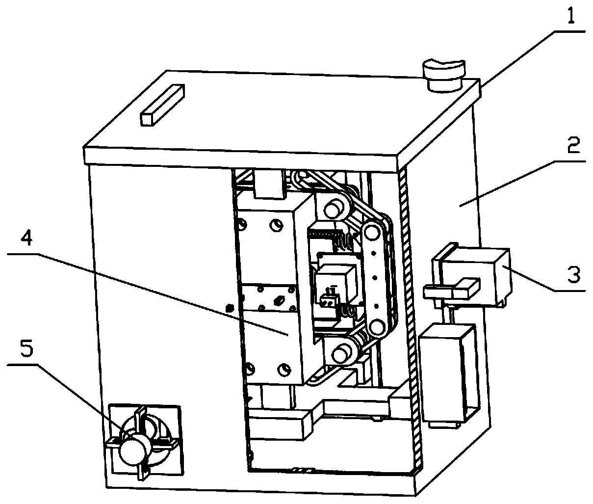
[0048] Combine below figure 1 , figure 2 , image 3 , Figure 4 , Figure 5 , Figure 6 , Figure 7 , Figure 8 , Figure 9 , Figure 10 , Figure 11 , Figure 12 , Figure 13 , Figure 14 , Figure 15 , Figure 16 , Figure 17 , Figure 18 , Figure 19 , Figure 20 , Figure 21 , Figure 22 , Figure 23 , Figure 24 , Figure 25 , Figure 26 , Figure 27 , Figure 28 , Figure 29 Describe this embodiment, the present invention relates to a sampling device, more specifically a large computer power supply protection device, including a protective cover 1, a protective box 2, an air supply valve 3, a circuit breaker 4, and a cooling fan 5, the device can Quickly feel the change of current in the circuit, and achieve the purpose of quick cut-off by controlling the solenoid valve, so as to protect the computer. The device can automatically cool the inside of the box during daily work, and the device can quickly eject carbon dioxide while breaking the cir...

specific Embodiment approach 2

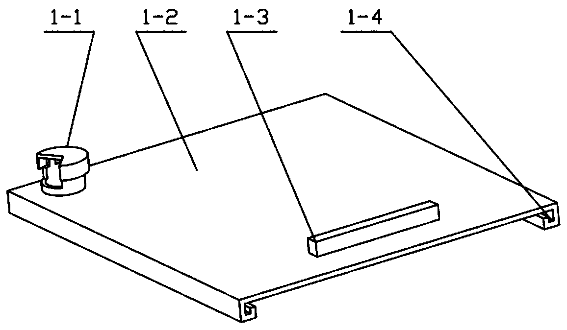
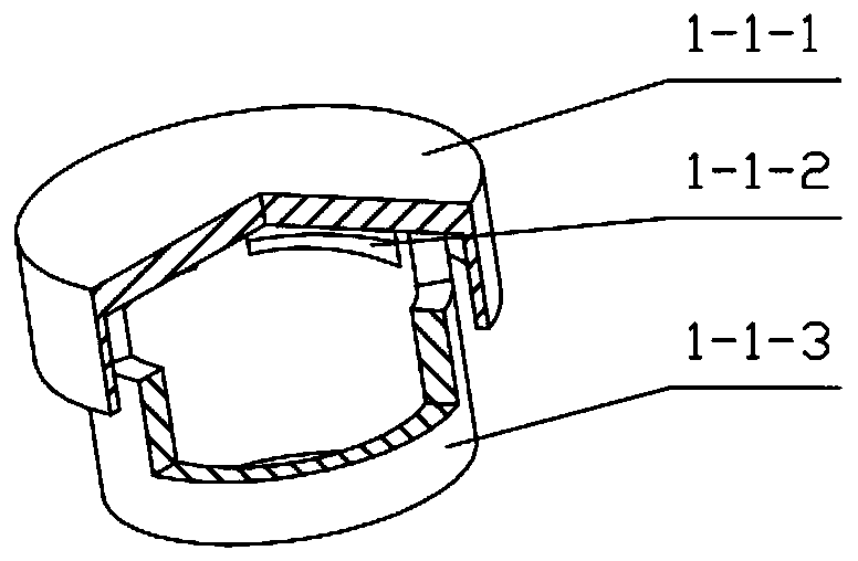
[0051] Combine below figure 1 , figure 2 , image 3 , Figure 4 , Figure 5 , Figure 6 , Figure 7 , Figure 8 , Figure 9 , Figure 10 , Figure 11 , Figure 12 , Figure 13 , Figure 14 , Figure 15 , Figure 16 , Figure 17 , Figure 18 , Figure 19 , Figure 20 , Figure 21 , Figure 22 , Figure 23 , Figure 24 , Figure 25 , Figure 26 , Figure 27 , Figure 28 , Figure 29 Describe this embodiment, this embodiment will further explain the first embodiment, the protective cover 1 includes a breathable cap 1-1, a cover plate 1-2, a push handle 1-3, a chute 1-4, a breathable cap 1-1 Located on the upper left part of the cover plate 1-2, the cover plate 1-2 is rectangular, the push handle 1-3 is rectangular, the push handle 1-3 is located on the upper part of the cover plate 1-2, the chute 1-4 is L-shaped, the chute 1 -4 is located on both sides of the cover plate 1-2; the breathable cap 1-1 includes a waterproof cap 1-1-1, a vent hole 1-1-2, a ...

specific Embodiment approach 3

[0053] Combine below figure 1 , figure 2 , image 3 , Figure 4 , Figure 5 , Figure 6 , Figure 7 , Figure 8 , Figure 9 , Figure 10 , Figure 11 , Figure 12, Figure 13 , Figure 14 , Figure 15 , Figure 16 , Figure 17 , Figure 18 , Figure 19 , Figure 20 , Figure 21 , Figure 22 , Figure 23 , Figure 24 , Figure 25 , Figure 26 , Figure 27 , Figure 28 , Figure 29 Describe this embodiment, this embodiment will further explain the first embodiment, the protective box 2 includes a box body 2-1, a limit chute 2-2, an air intake hole 2-3, a transmission hole 2-4, an air Bottle box 2-5, carbon dioxide cylinder 2-6, buffer pad 2-7, connecting column 2-8, air inlet 2-9, box body 2-1 is a cuboid, box body 2-1 top and cover plate 1- 2 are connected, four limit chutes 2-2 are provided, the limit chute 2-2 is in the vertical direction, the limit chute 2-2 is in contact with the circuit breaking mechanism 4, and the air inlet 2-3 is provided wit...


PUM


Abstract

The invention relates to a circuit protection device and particularly relates to large computer power supply protection equipment. The equipment comprises a protective cover, a protective box, an airsupply valve, a circuit breaking mechanism and a cooling fan. The device can quickly sense the change of current in a circuit, the purpose of fast cutting is achieved by controlling a solenoid valve,therefore, a computer is protected, the device can automatically cool the interior of a box body in daily work, the device can rapidly spray carbon dioxide to achieve the cooling and fire extinguishing effects while the circuit breaking is conducted, the protective cover is located on an upper portion of the protective box and is matched with the protective box, the air supply valve is located ona right side of the protective box, the circuit breaking mechanism is located in the protective box, the circuit breaking mechanism is in the protective box with a sliding fit, and the cooling fan islocated on a front portion of the protective box.

Description

technical field [0001] The invention relates to a circuit protection device, in particular to a large computer power supply protection device. Background technique [0002] The computer has become an indispensable item in people's life, and the computer also plays a vital role in the work, but due to the computer damage caused by the instability of the working voltage, in order to protect the computer, this large-scale Computer power supply protection equipment. Contents of the invention [0003] The technical problem mainly solved by the present invention is to provide a large-scale computer power supply protection device. The device can quickly sense the change of the current in the circuit. By controlling the solenoid valve, the purpose of fast cutting can be achieved, thereby protecting the computer. Cooling the inside of the box, the device can quickly eject carbon dioxide while breaking the circuit to achieve the effect of cooling and extinguishing fire. [0004] I...

Claims


Application Information

Patent Timeline
Patent Type & Authority Applications(China)
IPC IPC(8): H01H71/10H01H71/24H01H71/02H01H71/00H01H9/52G06F1/20G06F1/18A62C3/16A62C31/00
CPCA62C3/16A62C31/00G06F1/181G06F1/20H01H9/52H01H71/00H01H71/025H01H71/10H01H71/24
Inventor 周川
Owner 贵州云腾未来科技有限公司
Why Eureka
Try Eureka