Stamping die for conveniently adjusting distance

A technology of stamping die and distance adjustment, applied in the field of stamping processing, can solve the problems of instability, the accuracy of the lower die cannot be guaranteed, and the product accuracy is difficult to ensure, and achieves simple equipment structure, efficient and fast waste discharge, and efficient punching and processing. Effect

Active Publication Date: 2019-12-27
山东力创模具股份有限公司
View PDF7 Cites 2 Cited by
  • Summary
  • Abstract
  • Description
  • Claims
  • Application Information

AI Technical Summary

Problems solved by technology

[0002] The stamping die is an existing technology, and has the following disadvantages: During the use of the stamping die, especially the use of the lower die, the workpiece needs to be placed in the lower die, and then the workpiece is stamped by the stamping of the upper die In the process of operation, if it is necessary to change the shape and size of the parts, the lower mold must be replaced again. This not only wastes the time for personnel to replace the lower mold, but also makes the accuracy of the lower mold unable to be guaranteed, which reduces the accuracy of the product. The lower mold also has the problem of not being firm during use, requiring personnel to repeatedly clamp and fix the lower mold, which wastes a lot of time for the personnel and makes it difficult to guarantee the accuracy of the product, which makes the practicability of the equipment and The reliability is reduced. At the same time, the equipment adopts a single method for the processing of blanking materials, which cannot efficiently recover the blanking materials, which reduces the working efficiency of the equipment.

Method used


Image

  • Stamping die for conveniently adjusting distance
  • Stamping die for conveniently adjusting distance
  • Stamping die for conveniently adjusting distance

Examples


Embodiment Construction

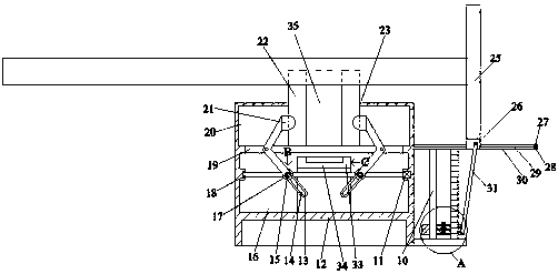
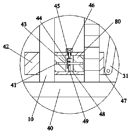
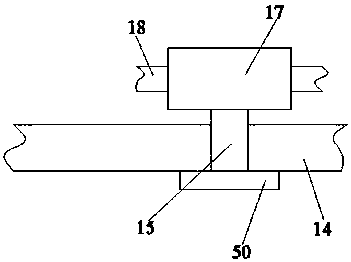
[0023] Such as Figure 1-Figure 5 As shown, the present invention is described in detail. For the convenience of description, the orientations mentioned below are now stipulated as follows: figure 1 The up, down, left, right, front and back directions of the projection relationship are consistent. A stamping die for easy distance adjustment of the present invention includes a side box 12. A transmission inner cavity 16 is arranged in the side box 12. The upper end wall of the transmission inner cavity 16 communicates with An intermediate cavity 19 is provided, the upper end wall of the intermediate cavity 19 is connected with a top cavity 20, the upper end wall of the top cavity 20 is connected with an opening cavity 23, and a lower mold 22 is installed in the opening cavity 23, so The lower mold 22 is provided with a penetrating blanking cavity 35, the lower mold 22 is against the lower end wall of the top cavity 20, and the transmission inner cavity 16, the middle cavity 19 ...


PUM


Abstract

The invention discloses a stamping die for conveniently adjusting distance. The stamping die for conveniently adjusting the distance comprises a side box, wherein a transmission inner cavity is arranged in the side box, an intermediate cavity is arranged in the upper end wall of the transmission inner cavity in a communicating mode, a top cavity is arranged in the upper end wall of the intermediate cavity in a communicating mode, an open cavity is arranged in the upper end wall of the top cavity in a communicating mode, a lower die is clamped in the open cavity, a through discharging cavity isarranged in the lower die, the lower die abuts against the lower end wall of the top cavity, a linkage fixing device for stably fixing the lower die is arranged in the transmission inner cavity, themiddle cavity and the top cavity, and a low side plate is fixedly arranged on the right end face of the side box. The stamping die is simple in structure, the size and distance can be conveniently adjusted during workpiece stamping, efficient stamping and machining of workpieces are achieved, the lower die is convenient to mount and replace and the structural intensity is improved as a connectionrod, a cam and other structures are used, and waste materials are discharged more efficiently and quickly.

Description

technical field [0001] The invention relates to the technical field of stamping processing, in particular to a stamping die for easy distance adjustment. Background technique [0002] The stamping die is an existing technology, and has the following disadvantages: During the use of the stamping die, especially the use of the lower die, the workpiece needs to be placed in the lower die, and then the workpiece is stamped by the stamping of the upper die In the process of operation, if it is necessary to change the shape and size of the parts, the lower mold must be replaced again. This not only wastes the time for personnel to replace the lower mold, but also makes the accuracy of the lower mold unable to be guaranteed, which reduces the accuracy of the product. The lower mold also has the problem of not being firm during use, requiring personnel to repeatedly clamp and fix the lower mold, which wastes a lot of time for the personnel and makes it difficult to guarantee the acc...

Claims


Application Information

Patent Timeline
Patent Type & Authority Applications(China)
IPC IPC(8): B21D28/14B21D45/06
CPCB21D28/14B21D45/06
Inventor 胡月明
Owner 山东力创模具股份有限公司
Why Eureka
Try Eureka