A device for punching holes in spherical glass products

A technology for glass products and punching devices, which is applied in the direction of manufacturing tools, work accessories, stone processing tools, etc., can solve the problems of increased difficulty, long processing time, unreliability, etc. The effect of enhancing the positioning accuracy

Active Publication Date: 2019-03-01
ZHONGSHAN CHUANGKE RES TECH SERVICE
View PDF8 Cites 0 Cited by
  • Summary
  • Abstract
  • Description
  • Claims
  • Application Information

AI Technical Summary

Problems solved by technology

With the industrialization and scale of glass production, glasses with various uses and performances have come out one after another, which has a huge impact on people's daily life. Nowadays, people's urban life cannot be separated from glass, and various glass products are extremely difficult. It has greatly enriched our commodity market. As people manufacture and use glass products more widely, there are more and more pursuits and usage methods for glass products, and spherical glass products are very popular among people. For glass products, due to its special shape, the professional level of the staff is extremely high, especially when processing and drilling spherical glass products, most of the workers manually punch holes with electric drills, which not only is cumbersome to measure and position, but also increases the work. It is very difficult, and it is very easy to miss the hole when punching, so the processing quality cannot be guaranteed. Not only the processing time is long, time-consuming and labor-intensive, but also the pass rate of the spherical glass products that have been punched is low. This punching method is inefficient. practical, unreliable

Method used


Image

  • A device for punching holes in spherical glass products
  • A device for punching holes in spherical glass products
  • A device for punching holes in spherical glass products

Examples


Embodiment Construction

[0019] Below in conjunction with accompanying drawing and specific embodiment the present invention is described in further detail:

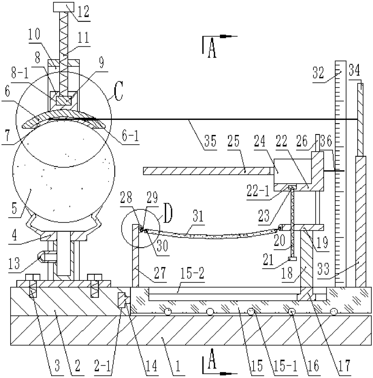
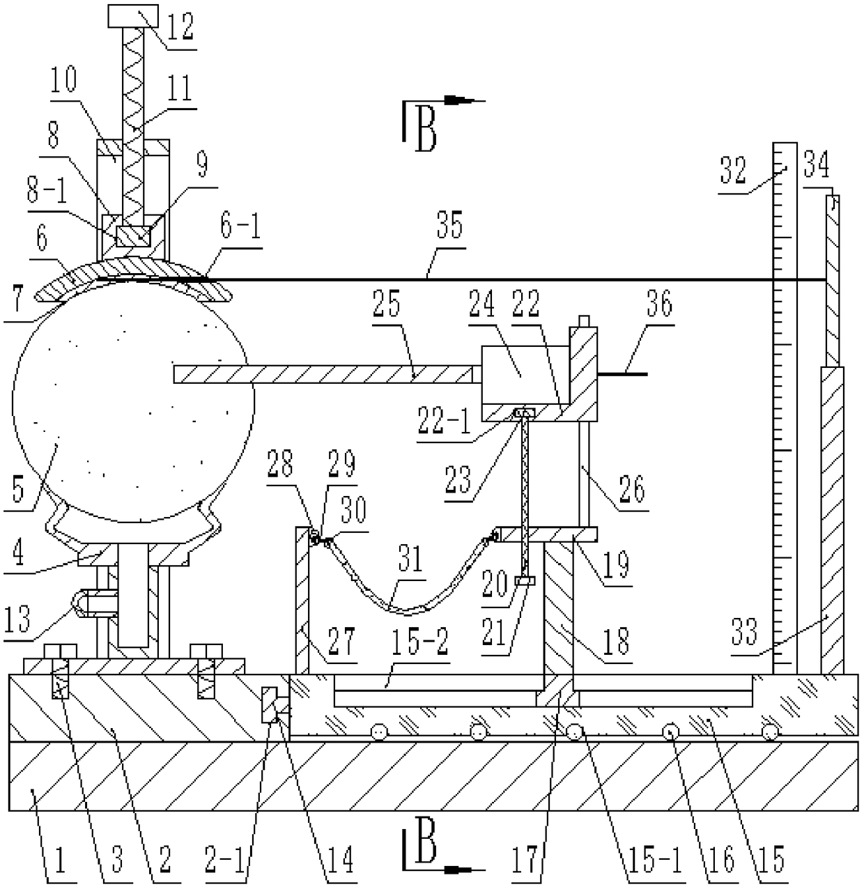
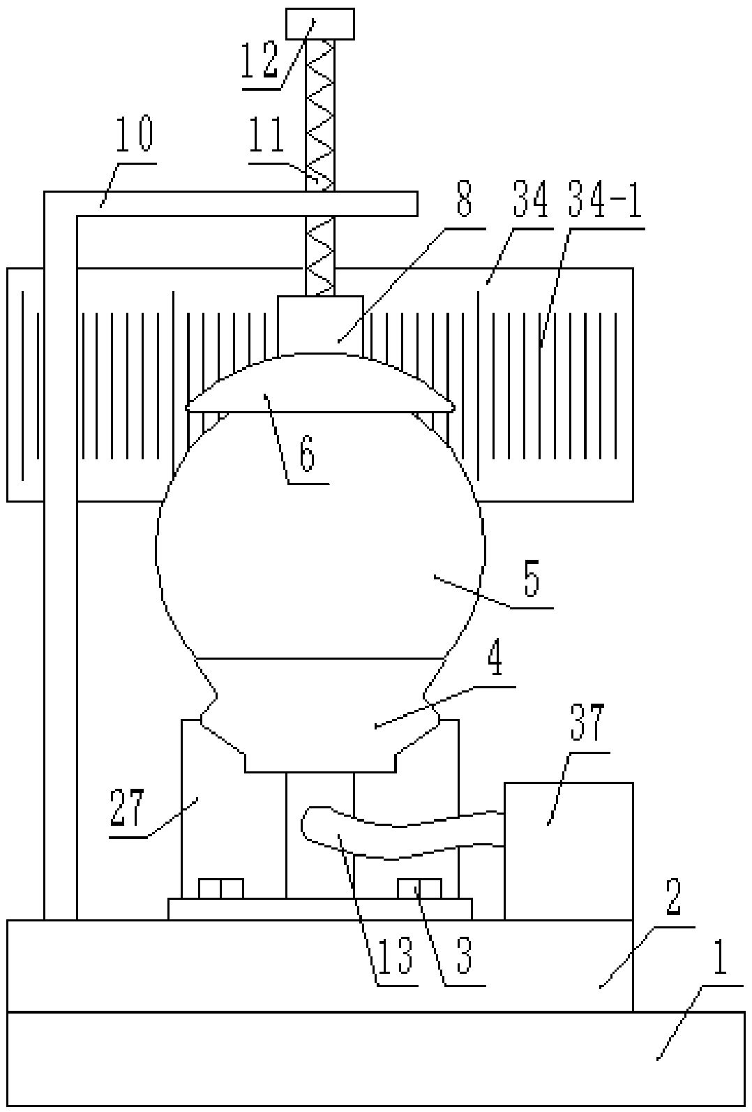
[0020] Such as Figure 1-Figure 8 As shown, a spherical glass product punching device includes a bottom plate 1, the top surface of the bottom plate 1 is fixed with a fixed plate A2, and the top surface of the fixed plate A2 is fixed with a vacuum suction cup 4 by bolts 3, and the vacuum suction cup 4 is provided with a spherical glass product 5, the top surface of the spherical glass product 5 is provided with an arc-shaped clamp block 6, the inner arc surface of the arc-shaped clamp block 6 is attached with a rubber layer 7, and the arc-shaped clamp block The side of the block 6 is provided with a through hole A6-1, and the inside of the rubber layer 7 is embedded with a pointer A35. Pass through, the top surface of the arc-shaped clamping block 6 is fixed with a fixed block A8, the top surface of the fixed block A8 is provided with a blind h...


PUM


Abstract

The invention discloses a perforating device for a spherical glass product. The perforating device comprises a bottom plate. A fixed plate A is fixed to the top face of the bottom plate. A vacuum suction cup is fixed to the top face of the fixed plate A through bolts. The spherical glass product is arranged above the vacuum suction cup. An arc clamping block is arranged on the top face of the spherical glass product. A rubber layer is attached to the inner arc face of the arc clamping block. A through hole A is formed in the side face of the arc clamping block. A pointer A is embedded in the rubber layer. According to the perforating device, the arc clamping block and the vacuum suction cup are designed to cooperate to fix the spherical glass product, machining and perforating are convenient, and the perforating percent of pass is improved; in the process of moving a drill bit, the perforating position is located by observing the moving amount of the pointer A and the moving amount ofa pointer B, the locating speed is high, time and labor are saved, and the locating precision of a hole is enhanced; during perforating, a T-shaped sliding block B moves in a sliding groove B to enable the drill bit to perforate the spherical glass product, one-time forming is achieved, and the machining quality of the hole is improved; and the perforating device is high in efficiency, practical and reliable.

Description

【Technical field】 [0001] The invention relates to the field of glass processing equipment, in particular to a spherical glass product drilling device. 【Background technique】 [0002] Glass has become an important material in daily life, production and science and technology. With the industrialization and scale of glass production, glasses with various uses and performances have come out one after another, which has a huge impact on people's daily life. Nowadays, people's urban life cannot be separated from glass, and various glass products are extremely difficult. It has greatly enriched our commodity market. As people manufacture and use glass products more widely, there are more and more pursuits and usage methods for glass products, and spherical glass products are very popular among people. For glass products, due to its special shape, the professional level of the staff is extremely high, especially when processing and drilling spherical glass products, most of the wo...

Claims


Application Information

Patent Timeline
Patent Type & Authority Patents(China)
IPC IPC(8): B28D1/14B28D7/00B28D7/04
CPCB28D1/14B28D7/00B28D7/046
Inventor 粟婷陈路玉杜瑞婷
Owner ZHONGSHAN CHUANGKE RES TECH SERVICE
Why Eureka
Try Eureka