Swing push-pull hob tool system and tool-changing method thereof

A cutting tool system and hob technology, applied in earthwork drilling, mining equipment, tunnels, etc., can solve the problems of low cooperation and low automation of tool changing robots, reduce the risk of manual tool changing, and achieve a high degree of automation , Improve the effect of construction safety factor

Inactive Publication Date: 2019-12-27
CHINA RAILWAY ENGINEERING EQUIPMENT GROUP CO LTD
View PDF5 Cites 1 Cited by
  • Summary
  • Abstract
  • Description
  • Claims
  • Application Information

AI Technical Summary

Problems solved by technology

[0003] In view of the deficiencies in the above-mentioned background technology, the present invention proposes a swinging push-pull hob tool system and its tool changing method, which solves the problems of low degree of automation of tool changing and low degree of cooperation with tool changing robots in the prior art

Method used


Image

  • Swing push-pull hob tool system and tool-changing method thereof
  • Swing push-pull hob tool system and tool-changing method thereof
  • Swing push-pull hob tool system and tool-changing method thereof

Examples


Embodiment 1

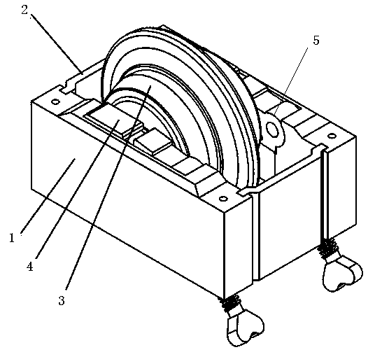
[0025] Example 1, such as figure 1 As shown, a swing push-pull hob cutter system includes a cutter box 1 and a hob 3. The hob is located in the cutter box and is detachably connected to the cutter box. The two ends of the cutter box 1 are clamped with connecting plates 2 for connecting The plate 2 is detachably connected with the knife box 1 to realize the sealing of the knife box. The inner walls on both sides of the knife box 1 are provided with a block 4 for fixing the hob cutter shaft 6 and a swing push-pull locking mechanism 5 , and the block 4 corresponds to the swing push-pull lock mechanism 5 . During installation, the hob cutter shaft is located between the block and the swing push-pull locking mechanism, and whether the hob cutter shaft is pressed or not is realized through the up and down swing movement of the swing push-pull lock mechanism.

[0026] further, such as figure 2 As shown, the clamping block 4 is fixedly connected with the cutter box 1 through the fa...

Embodiment 2

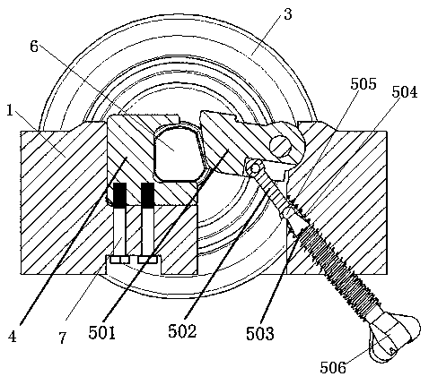
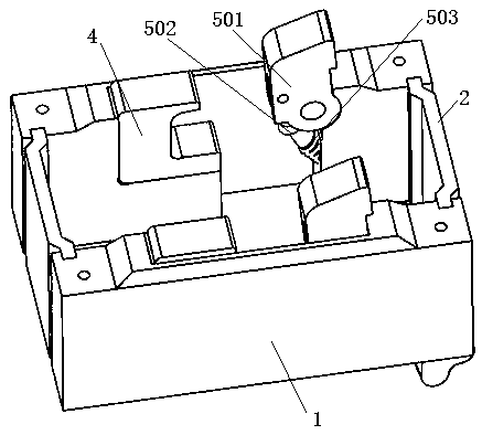
[0029] Example 2, such as Figure 5 , 6 A swinging push-pull hob cutter system is shown, the inside of the knife box 1 is provided with a mounting groove 8, and the bottom of the mounting groove 8 is provided with a mounting hole 9, and the mounting hole 9 cooperates with the swinging push-pull locking mechanism 5. The swinging push-pull locking mechanism 5 cooperates with the installation groove, and the swing pressing block 501 of the swinging push-pull locking mechanism is hinged with the tool box 1, and the positioning swing push-pull locking mechanism and its direction of motion realize quick tool change.

[0030] Further, the swinging push-pull locking mechanism 5 includes a swinging pressing block 501 and a push-pull rod 5-2, the swinging pressing block 501 is located in the installation groove 8, and the swinging pressing block 501 is hinged with the tool box 1, and the pressing edge of the swinging pressing block 501 is connected to the The hob cutter shaft cooperate...

Embodiment 3

[0035] Example 3, such as Figure 7 , 8 As shown, a swinging push-pull hob cutter system, the mounting hole 9 is a vertical through hole, the push-pull rod 5-2 includes an upper connecting rod 201, a middle connecting rod 202 and a lower screw 203, and the two ends of the middle connecting rod 202 They are respectively hinged with the upper connecting rod 201 and the lower screw rod 203, and the upper connecting rod 201, the middle connecting rod 202 and the lower screw rod 203 are all matched with the vertical through holes. The upper connecting rod 201 is rotatably arranged in the light hole, and the lower screw rod 203 is located in the vertical through hole and fixed by a locking nut.

[0036] Other structures are the same as in Embodiment 2.

[0037] The tool changing method of the above-mentioned swinging push-pull hob tool system is characterized in that it includes the following steps: S1: tool disassembly: the tool changing robot reversely turns the lock nut, and th...


PUM


Abstract

The invention discloses a swing push-pull hob tool system and a tool-changing method thereof, and solves the problems of low tool-changing automation degree of a tool and low cooperation degree of a tool-changing robot in the prior art. The swing push-pull hob tool system comprises a tool box and a hob, a clamping block used for clamping and fixing a tool shaft of the hob and a swing push-pull locking mechanism are arranged on the inner walls of the two sides of the tool box correspondingly, and the clamping block corresponds to the swing push-pull locking mechanism. The swing push-pull hob tool system adopts the swing push-pull locking mechanism and the tool-changing robot to achieve the high cooperation degree, the swing push-pull locking mechanism is controlled through the tool-changingrobot, a swing pressing block is driven to swing up and down through a push-pull rod ( or a thread rod) by rotating a locking nut (or a rotating handle), pressing of the swing pressing block on the tool shaft of the hob is achieved, fast and precise tool changing is achieved, and the tool changing efficiency is improved.

Description

technical field [0001] The invention relates to the technical field of shield tunneling cutters, in particular to a swinging push-pull hob cutter system and a cutter changing method thereof. Background technique [0002] During the construction process of the full-face tunnel boring machine, the tool consumption is large and the replacement is frequent. The tool change operation time accounts for more than 10% of the tunnel construction cycle. The existing tool change work mainly relies on manual work, and the construction environment such as large buried depth and high water pressure There are great safety hazards in the underground operation, and major safety accidents such as casualties are prone to occur. According to statistics, nearly 70% of tunnel construction safety accidents in China are directly related to manual tool change operations. The international industry problem of "tool change risk" has become a bottleneck restricting the safety and efficiency of tunnel c...

Claims


Application Information

Patent Timeline
IPC IPC(8): E21D9/087E21D9/08
CPCE21D9/08E21D9/087
Inventor 王杜娟姜礼杰于庆增钱豪赵梦媛杨航原晓伟
Owner CHINA RAILWAY ENGINEERING EQUIPMENT GROUP CO LTD
Why Eureka
Try Eureka