
Decorative lamp and manufacturing method thereof

A technology for decorative lamps and wicks, which is applied in decorative art, special patterns, lighting devices, etc., can solve the problems of unfavorable automation degree, meager profit of decorative lamps, and automatic transformation of production processes, so as to achieve low cost of automation transformation, facilitate automation transformation, and facilitate The effect of installation and removal

Inactive Publication Date: 2019-12-27
DONGGUAN KAILANG IND
View PDF4 Cites 0 Cited by
  • Summary
  • Abstract
  • Description
  • Claims
  • Application Information

AI Technical Summary

Problems solved by technology

[0008] Both the injection molding and sealing types require expensive injection molding equipment, and the meager profits of decorative lights are not enough to support the automation of the production process, so this process still requires a large number of workers for assembly.
[0009] Embedded means that the wire is passed through the installation shell first, then the wick and the wire are welded together, and then the isolation part is placed between the poles of the wick, and the wick is installed in the direction opposite to the direction in which the wire passes through the installation shell. On the mounting shell, this process does not involve any heat processing process in the production process, the process is simple, and part of the process can be replaced by automated equipment. Therefore, the embedded decorative lamp is the largest decorative lamp in the market at present, but due to the Due to the unique installation characteristics, if you want to install the lampshade on the decorative lamp, it is difficult to adapt to the installation of the lampshade after modification on the original equipment. Therefore, the current practice in the industry is to install the lampshade manually by the workers after the entire lamp module is packaged. , which is not conducive to improving the degree of automation. At the same time, a new type of decorative lamp and related manufacturing processes are urgently needed in the industry

Method used


Image

  • Decorative lamp and manufacturing method thereof
  • Decorative lamp and manufacturing method thereof
  • Decorative lamp and manufacturing method thereof

Examples


Embodiment Construction

[0033] The present invention will be further elaborated below in conjunction with accompanying drawing:

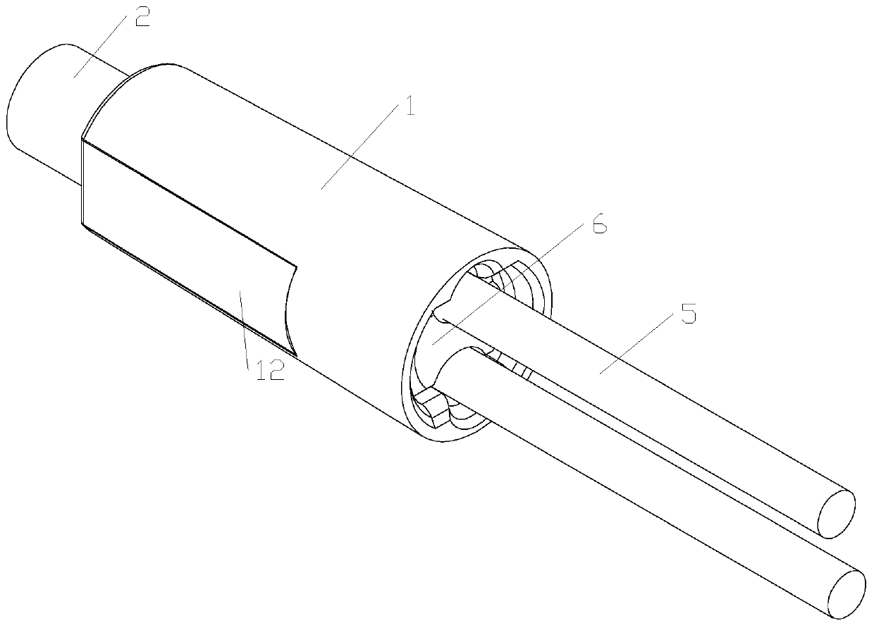
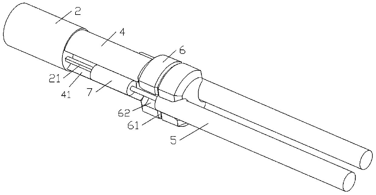
[0034] Such as figure 1 , figure 2 As shown, a decorative lamp includes a mounting shell 1, a wick 2, an insulating block 4, a tail plug 6 and a wire 5 for connecting to the pole pins of the wick 2, and the wick 2 has two pole pins.

[0035] Such as Figure 4 , Figure 5 As shown, the mounting shell 1 is a vertebral platform whose radius gradually decreases from the rear end face to the front end face, the mounting shell 1 has a through hole 11 that runs through the front and rear end faces, and the outer wall of the mounting shell 1 is provided with a stepped structure 12. The step structure 12 includes a horizontal surface 122 for positioning and a clamping surface 121 for fixing, and the installation shell 1 is made of elastic material.

[0036] Such as figure 1 , figure 2 As shown, the front end of the through hole 11 is pierced with a wick 2, and the tail of t...


PUM


Abstract

The invention relates to a decorative lamp and a manufacturing method thereof; a mounting shell is included; a through hole penetrating through the front and rear end surfaces is formed in the mounting shell; a lamp wick is arranged on the front end face of the through hole in a penetrating mode, the rear end face of the lamp wick is arranged in the through hole, an isolation block and a tail plugare sequentially arranged on the rear end face of the lamp wick in the penetrating direction of the lamp wick, a clamping ring is arranged on the surface of the tail plug in a protruding mode, and aclamping ring groove matched with the clamping ring is concavely formed in the through hole. The shape of the tail plug is matched with the shape of the through hole, the tail plug is concavely provided with a first wire slot for a guide to penetrate through; a second wire slot matched with the first wire slot is concavely formed in the mounting shell, and a wire connected with the lamp wick polefoot can be discharged from a circular channel formed by the first wire slot and the second wire slot; a step structure is arranged on the outer side wall of the mounting shell; by improving the structure and process, the lamp wick is installed in the mode that the head penetrates through the mounting shell when the lamp wick is installed, and automation of production is facilitated.

Description

technical field [0001] The invention relates to the technical field of lighting appliances, in particular to a decorative lamp and a manufacturing method thereof. Background technique [0002] At present, the decorative lamps on the market can be divided into two types: contact type and welding type according to the connection form of the wick: [0003] Contact type, its main structure is to connect the wire and the terminal on the lamp housing together, and then contact the pole pin of the wick with the terminal, conduct electricity through contact conduction, when the wick is damaged, the wick can be easily disassembled and replaced with a new one The wick, so this structure is also called replaceable, but because the terminal and the pole of the wick are not fixedly connected, the terminal or the pole is easy to rust after long-term use or in a humid environment. In the case of rust, it is difficult for ordinary consumers to repair it by themselves. Usually, they can onl...

Claims


Application Information

Patent Timeline
Patent Type & Authority Applications(China)
IPC IPC(8): F21S8/00F21V21/00F21V23/00F21V19/00F21W121/00
CPCF21S8/00F21V19/00F21V21/00F21V23/002F21W2121/00
Inventor 黄开朗周国安
Owner DONGGUAN KAILANG IND
Learn More