Eureka AIR delivers breakthrough ideas for toughest innovation challenges, trusted by R&D personnel around the world.

Anti-loosening optical-fiber connector plug shell body

A technology for optical fiber connectors and plug housings, which is applied in the field of anti-loose optical fiber connector plug housings and anti-loose optical fiber connector plugs, can solve the problems of poor reliability and low structural strength of anti-loose optical fiber connectors, and achieve improved strength and reliability effects

Active Publication Date: 2019-12-27
CHINA AVIATION OPTICAL-ELECTRICAL TECH CO LTD
View PDF6 Cites 1 Cited by
  • Summary
  • Abstract
  • Description
  • Claims
  • Application Information

AI Technical Summary

Problems solved by technology

[0005] The purpose of the present invention is to provide an anti-loose fiber optic connector plug housing to solve the problems of low structural strength and poor reliability of the anti-loose optical fiber connector in the prior art; connector plug to solve the problems of low structural strength and poor reliability of the anti-loose optical fiber connector in the prior art

Method used


Image

  • Anti-loosening optical-fiber connector plug shell body
  • Anti-loosening optical-fiber connector plug shell body
  • Anti-loosening optical-fiber connector plug shell body

Examples


Embodiment Construction

[0023] Embodiments of the present invention will be further described below in conjunction with the accompanying drawings.

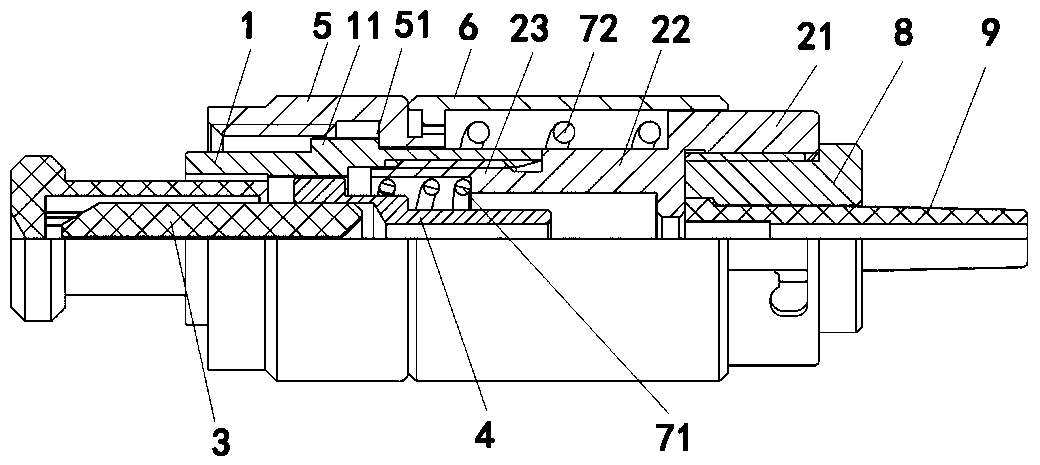
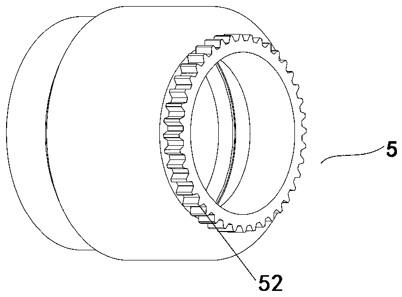
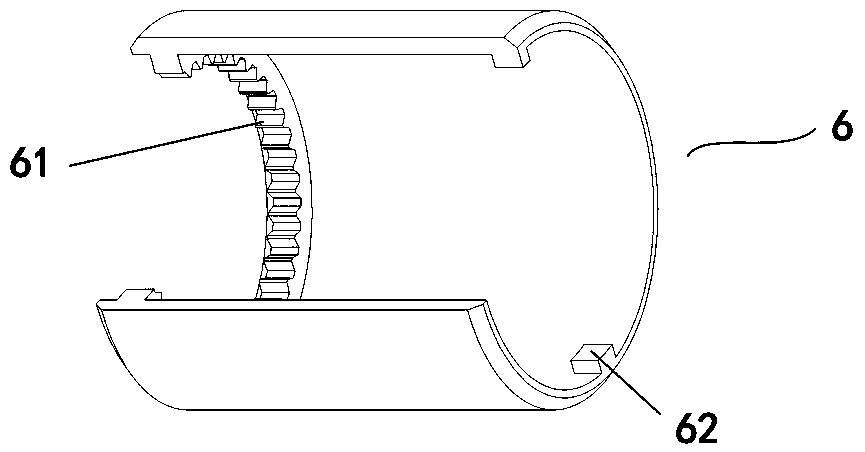
[0024] A specific embodiment of the anti-loosening optical fiber connector plug housing of the present invention, such as figure 1 As shown, the optical fiber connector includes a front sleeve 1 and a rear sleeve 2. The front sleeve 1 and the rear sleeve 2 are connected together by threads, and the inner cavities of the front sleeve 1 and the rear sleeve 2 are used for ferrule components. definition figure 1 The middle left end is the front end, the ferrule part includes the ceramic ferrule 3, which is used to insert the fiber core of the optical fiber, the rear of the ceramic ferrule 3 is the flange 4, and the front end of the flange 4 is set outside the rear end of the ceramic ferrule 3, The outer peripheral surface of the flange 4 and the inner peripheral surface of the rear sleeve 2 are both stepped structures, and a spring 71 is arranged between th...


PUM


Abstract

The invention relates to an anti-loosening optical-fiber connector plug shell body and an anti-loosening optical-fiber connector plug. The anti-loosening optical-fiber connector plug shell body includes a front sleeve and a rear sleeve assembled together in a thread manner. A connection nut is arranged outside the front sleeve in a sleeving manner, and is used for thread connection with a socket.A locking shell body is assembled outside the rear sleeve in a sliding guiding manner. A connection nut rotation preventing structure is arranged between the connection nut and the locking shell body.The locking shell body has a locking position and an unlocking position in a moving stroke thereof. The locking shell body rotation preventing structure is arranged between the rear sleeve and the locking shell body. Springs are arranged between the rear sleeve and the locking shell body. Compared with arranging a notch at a thread section of the front sleeve to realize rotation preventing assembly of the locking shell body with the front sleeve and the rear sleeve, the embodiment of the invention arranges the locking shell body rotation preventing structure on the rear sleeve, cannot impactconnection of the front sleeve and the rear sleeve, and guarantees improvement of strength and reliability of the optical-fiber connector plug on the premise that an anti-loosening role can be played.

Description

technical field [0001] The invention relates to an anti-loose optical fiber connector plug shell and an anti-loose optical fiber connector plug. Background technique [0002] FC fiber optic connector assembly is a common fiber optic connector assembly, the plug and socket in this connector assembly are connected together through a threaded connector. Because it is a standard connector, the FC fiber optic connector assembly has been widely used, but in some environments where there are factors such as vibration and shock, it is not reliable to fix the plug and the socket together only through threaded connection. [0003] The Chinese invention patent with the authorized announcement number CN104503034B and the authorized announcement date of 2018.01.05 discloses a loose-proof optical fiber connector. The optical fiber connector includes a front sleeve and a rear sleeve, optical fibers and ceramic ferrules for inserting optical fibers. In the nest and the rear sleeve, the fro...

Claims


Application Information

Patent Timeline
Patent Type & Authority Applications(China)
IPC IPC(8): G02B6/38
CPCG02B6/3807G02B6/3869G02B6/3871G02B6/3894
Inventor 汤洋陈晓林杨金玉
Owner CHINA AVIATION OPTICAL-ELECTRICAL TECH CO LTD
Why Eureka
Eureka Blog
Learn More