Positioning block, optical positioning system based on positioning block, optical positioning method based on positioning block, and functional module

An optical positioning and positioning block technology, applied in the optical field, can solve the problems of wasting time and energy, consuming a lot of work, and the system is not repeatable.

Active Publication Date: 2019-12-27
JIAXING XURUI ELECTRONICS TECH CO LTD
View PDF28 Cites 8 Cited by
  • Summary
  • Abstract
  • Description
  • Claims
  • Application Information

AI Technical Summary

Problems solved by technology

[0002] At present, in the laboratory, when the optical system is built, it is necessary to use a multi-dimensional adjustment frame to adjust the optical path of the system. In some complex optical systems, it takes a lot of work to build the optical path.
Moreover, due to the high degree of freedom of the optical path, the system is almost non-repeatable. Every time the optical path structure changes, the system needs to be adjusted again, wasting a lot of time and energy

Method used


Image

  • Positioning block, optical positioning system based on positioning block, optical positioning method based on positioning block, and functional module
  • Positioning block, optical positioning system based on positioning block, optical positioning method based on positioning block, and functional module
  • Positioning block, optical positioning system based on positioning block, optical positioning method based on positioning block, and functional module

Examples


Embodiment 1-1

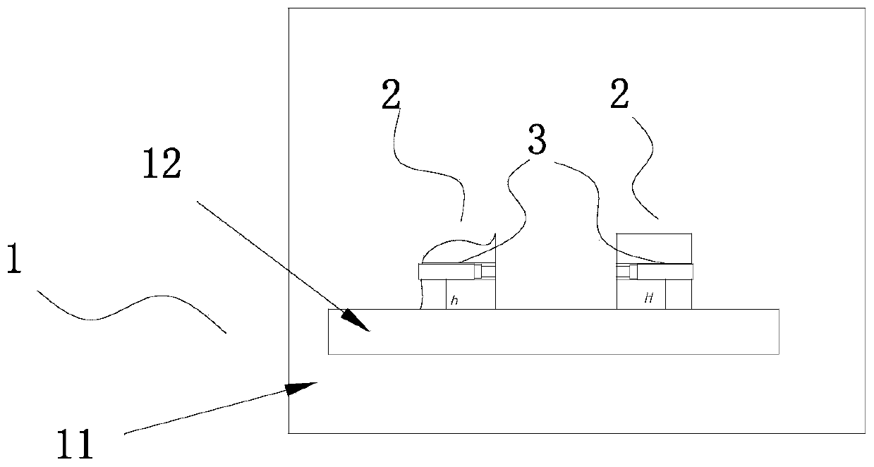
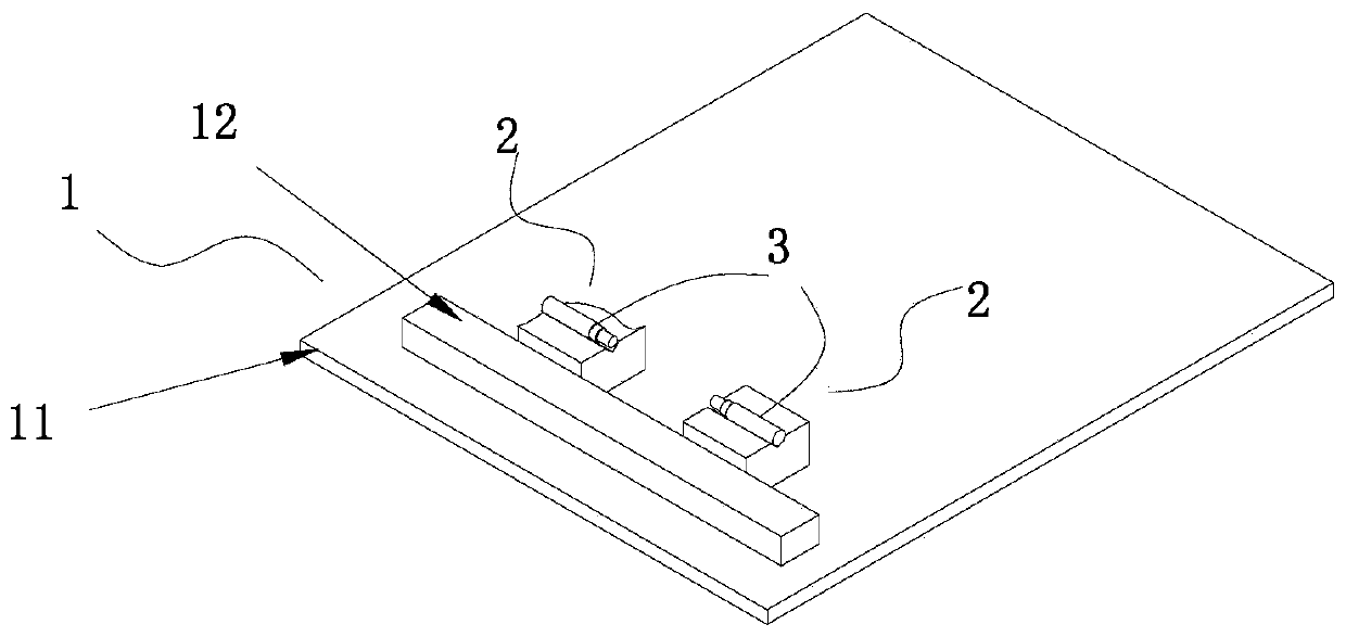
[0046] like figure 1 and figure 2 , an optical positioning system based on positioning blocks. It includes a positioning disc 1 and two positioning blocks 2 for positioning. The positioning plate 1 is composed of a bottom plate 11 with a horizontal upper surface and a straight inner side as a positioning side body 12; the block 2 includes a bottom surface and a positioning side, and the upper surface is used for carrying optical components. The optical components in this embodiment is the collimator.

[0047] The positioning method using the positioning system of the present embodiment is: take the base plate 11 of the positioning plate 1 as the positioning reference in the vertical (height) direction, and take the positioning side of the body 12 on the base plate 11 as the positioning reference in the horizontal direction. The bottom surface of the positioning block fits with the base plate 11 and the upper surface to realize the positioning in the vertical direction; the...

Embodiment 1-2

[0050] Present embodiment has no accompanying drawing, can refer to embodiment 2-2 Figure 5 .

[0051] In the present embodiment, the body and the base plate are inseparable. The difference from the embodiment 1-1 is that a movable carrier 3 is added on the bottom plate, and one side of the carrier 3 is attached to the positioning side of the leaning body 12 . The bottom surface of the positioning block 2 is attached to the carrier board 3 .

[0052] In this embodiment, the positioning plate 1 adopts non-magnetic material, and the carrier plate 3 adopts magnetic material, so that the block 2 and the carrier plate 3 are adsorbed as a whole, but not adsorbed with the positioning plate, so that the carrier plate 3 and the block 2 and The optical functional components are moved out of the positioning plate as a whole to form an independent functional module. Glue can also be used to fix the positioning block 2 and the carrier plate 3, and the carrier plate 3, the block 2 and t...

Embodiment 2-1

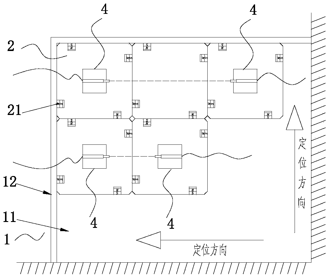
[0054] like image 3 and Figure 4 , an optical positioning system based on positioning blocks. It includes a positioning plate 1 and several blocks 2 for positioning. Positioning plate 1 is made of the base plate 11 of upper surface level and the straight inner side body 12 that is perpendicular to each other; The plane of each block 2 in the figure is the square of the same size, and the plane size can also be designed by modularization, that is, the plane size is as follows: A square with the minimum side length is the basic unit, and a rectangle or square whose length or width is an integral multiple of the minimum side length can be designed.

[0055] Block 2 adopts magnetic stainless steel or other magnetic materials, and is integrally processed and formed. Each side of the cube 2 is embedded with a magnet 21 . The position of the magnets 21 avoids the middle position, and is unified to the left or to the right, and the polarity directions of the embedded magnets 21 ...


PUM


Abstract

The invention provides a positioning block, an optical positioning system based on the positioning block, an optical positioning method based on the positioning block, and a functional module, whereinthe positioning system comprises a bottom plate, at least one leaning body and a plurality of positioning blocks, wherein the upper surface of the bottom plate is horizontal; the leaning body has theflat and straight positioning side edge; the positioning blocks are used for loading optical assemblies and positioning; and a movable carrying plate can also be arranged on the bottom plate. The positioning in the vertical direction is realized by tightly attaching the bottoms of the positioning blocks with the bottom plate or the carrying plate; and the position positioning in the horizontal direction is realized by attaching the side surfaces of the positioning blocks to the positioning side of the leaning body. According to different light path designs, the optical assemblies are loaded on the positioning blocks in required positions; through connecting structures, the center points of all optical assemblies are positioned at the same height; light emitting assemblies are mechanicallyregulated, so that emergent light is parallel to the side surfaces and the bottom surfaces of the positioning blocks; and the center points of other optical assemblies are identical to the height ofthe emergent light. The basically accurate positioning of an optical system is realized.

Description

technical field [0001] The invention belongs to the field of optical technology, and relates to a positioning system and method for each optical functional component in an optical path, in particular to an optical positioning system and method based on a positioning block and a functional module. Background technique [0002] At present, in the laboratory, when building an optical system, it is necessary to use a multi-dimensional adjustment frame to adjust the optical path of the system. In some complex optical systems, it takes a lot of work to build the optical path. Moreover, because the degree of freedom of the optical path is too high, the system is almost non-repeatable. Every time the structure of the optical path changes, the system needs to be adjusted again, wasting a lot of time and effort. In order to overcome the deficiencies of the prior art, the present invention provides an optical positioning system and method using a positioning block as well as a position...

Claims


Application Information

Patent Timeline
Patent Type & Authority Applications(China)
IPC IPC(8): G02B7/00
CPCG02B7/00G02B7/003G02B6/42G02B7/004
Inventor 金新刚
Owner JIAXING XURUI ELECTRONICS TECH CO LTD
Why Eureka
Try Eureka