Image decomposition method and device
An image and two-dimensional image technology, applied in the field of image processing, can solve the problems that the decomposition method cannot distinguish between fine structures and textures, cannot remove the structure image texture, and the structure image is excessively smooth, so as to achieve good structure texture decomposition effect and structure Simple effect with few parameters
- Summary
- Abstract
- Description
- Claims
- Application Information
AI Technical Summary
Problems solved by technology
Method used
Image

Examples
Embodiment 1
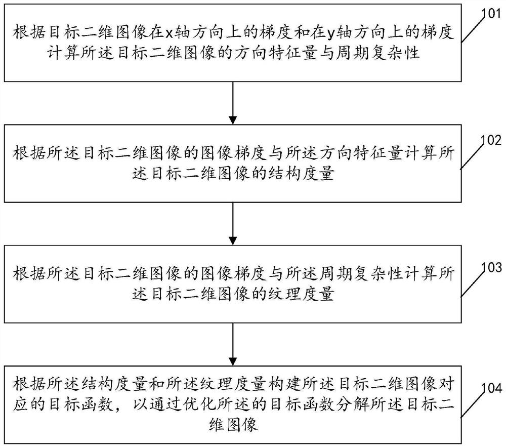
[0046] see figure 1 , figure 1 It is a schematic flowchart of an image decomposition method disclosed in Embodiment 1 of the present invention. Such as figure 1 As shown, the method includes the steps of:
[0047] 101. Calculate the directional feature quantity and periodic complexity of the target two-dimensional image according to the gradient in the x-axis direction and the gradient in the y-axis direction of the target two-dimensional image;
[0048] Specifically, calculate the direction feature quantity A of the target two-dimensional image according to formula (1) J , formula (1) is as follows:
[0049]
[0050] In this embodiment, as shown in formula (1), the eigenvalues of the structure tensor matrix include the first eigenvalue λ 1 and the second eigenvalue λ 2 , where, when the gradient of the target two-dimensional image has a main direction,
[0051] lambda 1 >> lambda 2 , then A J tends to 1, when the gradient of the target two-dimensional image is ...
Embodiment 2
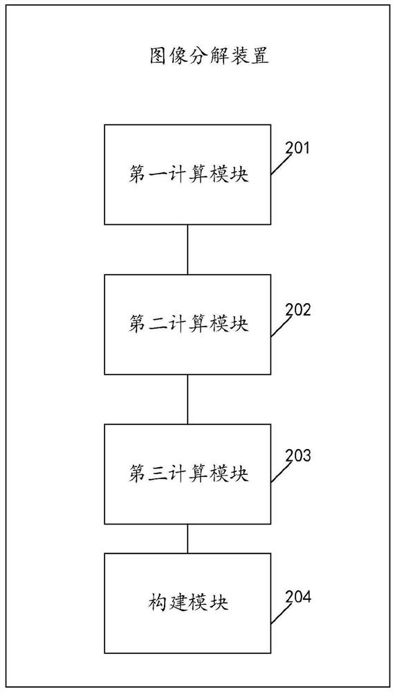
[0075] see figure 2 , figure 2 It is a schematic structural diagram of an image decomposition device provided by an embodiment of the present invention. Such as figure 2 As shown, the device includes a first calculation module 201, a second calculation module 202, a third calculation module 203, and a construction module 204, wherein:
[0076] The first calculation module 201 is configured to calculate the directional feature quantity and periodic complexity of the target two-dimensional image according to the gradient of the target two-dimensional image in the x-axis direction and the gradient in the y-axis direction;
[0077] The second calculation module 202 is configured to calculate the structure metric of the target two-dimensional image according to the image gradient of the target two-dimensional image and the direction feature quantity;
[0078] The third calculation module 203 is configured to calculate the texture metric of the target two-dimensional image acc...
Embodiment 3
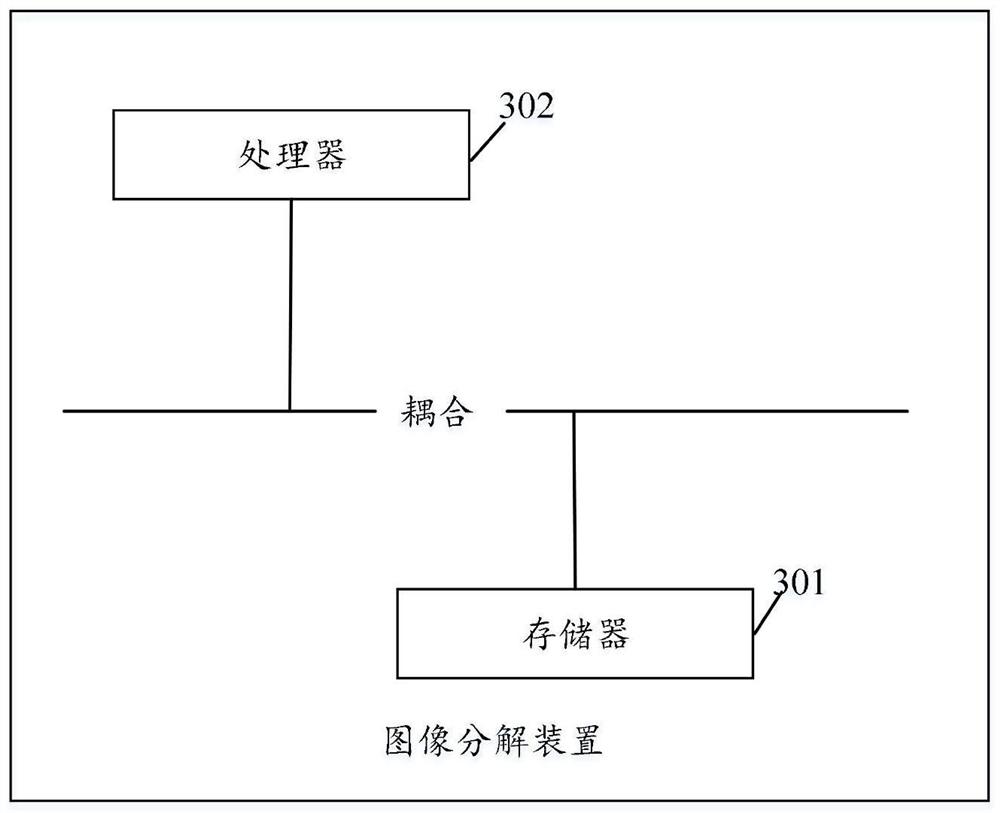
[0085] see image 3 , image 3 is a schematic structural diagram of an image decomposition device provided by an embodiment of the present invention, such as image 3 As shown, the image decomposition device includes:
[0086] At least one storage unit 301;
[0087] a processing unit 302 coupled to the at least one storage unit;
[0088] Wherein, the at least one storage unit 301 is used to store computer instructions;
[0089] The processing unit 302 is configured to invoke the computer instructions to execute the image decomposition method described in the first aspect of the present invention.
[0090]The image decomposition device of the present invention can decompose the target two-dimensional image based on the structure and texture metrics of the target two-dimensional image by executing the image decomposition method, and optimize the objective function of the target two-dimensional image through a neural network, wherein the structure The metric can preserve the...
PUM
 Abstract
Description
Claims
Application Information
 - R&D
- Intellectual Property
- Life Sciences
- Materials
- Tech Scout
- Unparalleled Data Quality
- Higher Quality Content
- 60% Fewer Hallucinations
Browse by: Latest US Patents, China's latest patents, Technical Efficacy Thesaurus, Application Domain, Technology Topic, Popular Technical Reports.
© 2025 PatSnap. All rights reserved.Legal|Privacy policy|Modern Slavery Act Transparency Statement|Sitemap|About US| Contact US: help@patsnap.com