
Current multiplexing radio frequency front end structure

A radio frequency front-end and current multiplexing technology, which is applied in the direction of electrical components, advanced technology, power management, etc., can solve the problems of high DC power consumption of the radio frequency front-end structure, which is not suitable for low-power applications of wireless sensor network systems, and realizes Low power consumption application, the effect of ensuring RF performance

Active Publication Date: 2019-12-27
SHANGHAI HUAHONG GRACE SEMICON MFG CORP
View PDF15 Cites 1 Cited by
  • Summary
  • Abstract
  • Description
  • Claims
  • Application Information

AI Technical Summary

Problems solved by technology

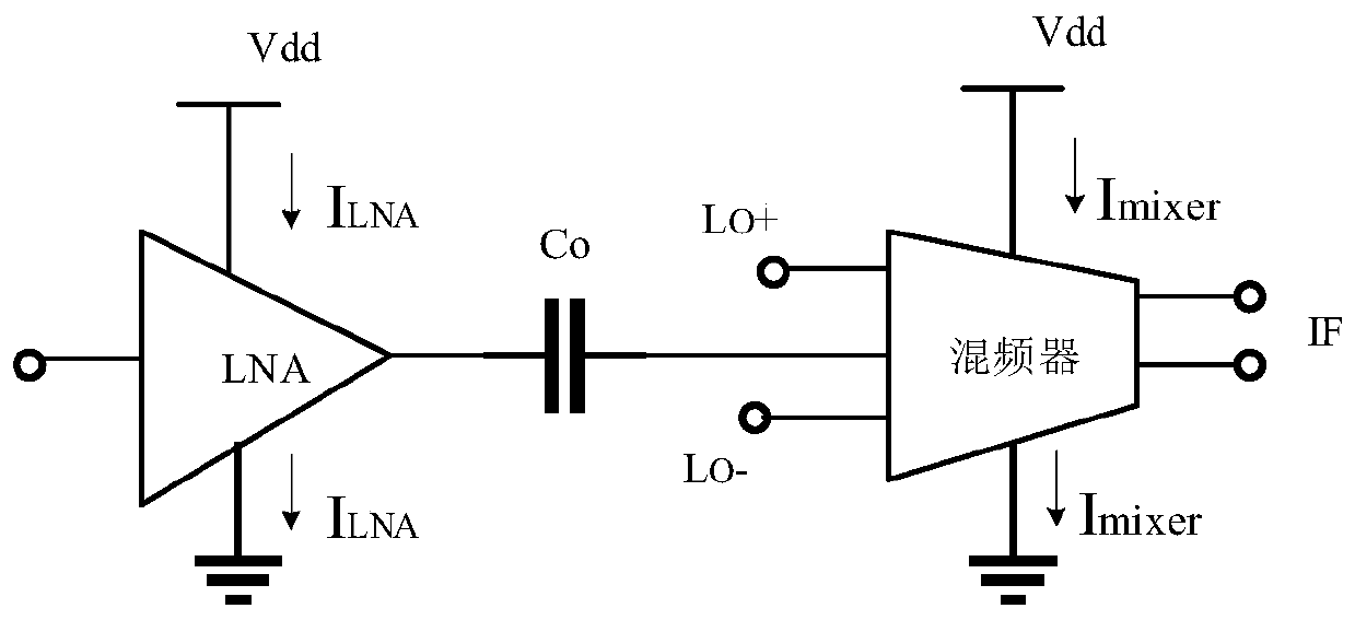
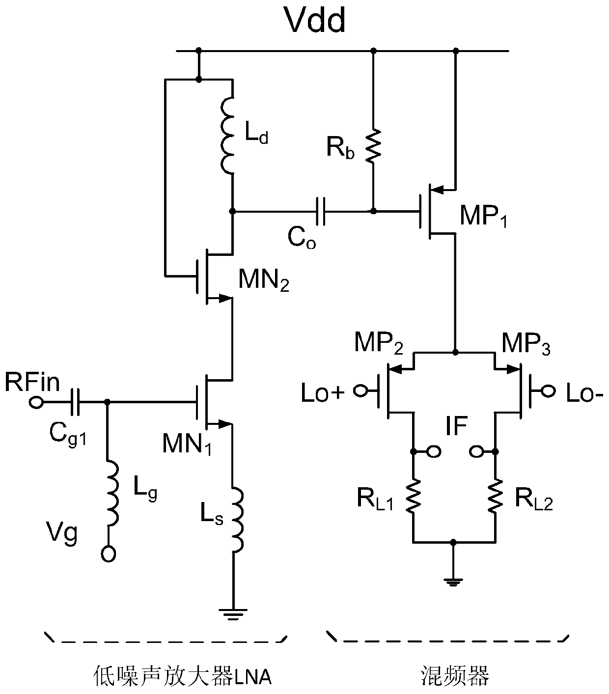
From Figure 1 and Figure 2 It can be seen that since the low noise amplifier and the mixer adopt independent static bias current, resulting in a large DC power consumption of the RF front-end structure, which is not suitable for low-power applications in wireless sensor network systems

Method used


Image

  • Current multiplexing radio frequency front end structure
  • Current multiplexing radio frequency front end structure
  • Current multiplexing radio frequency front end structure

Examples


Embodiment Construction

[0037] The technical solutions in this application will be clearly and completely described below in conjunction with the accompanying drawings. Apparently, the described embodiments are part of the embodiments of this application, not all of them. Based on the embodiments in this application, all other embodiments obtained by persons of ordinary skill in the art without making creative efforts belong to the scope of protection of this application.

[0038] In the description of this application, it should be noted that the terms "center", "upper", "lower", "left", "right", "vertical", "horizontal", "inner", "outer" etc. The indicated orientation or positional relationship is based on the orientation or positional relationship shown in the drawings, and is only for the convenience of describing the present application and simplifying the description, rather than indicating or implying that the referred device or element must have a specific orientation, use a specific orientati...


PUM


Abstract

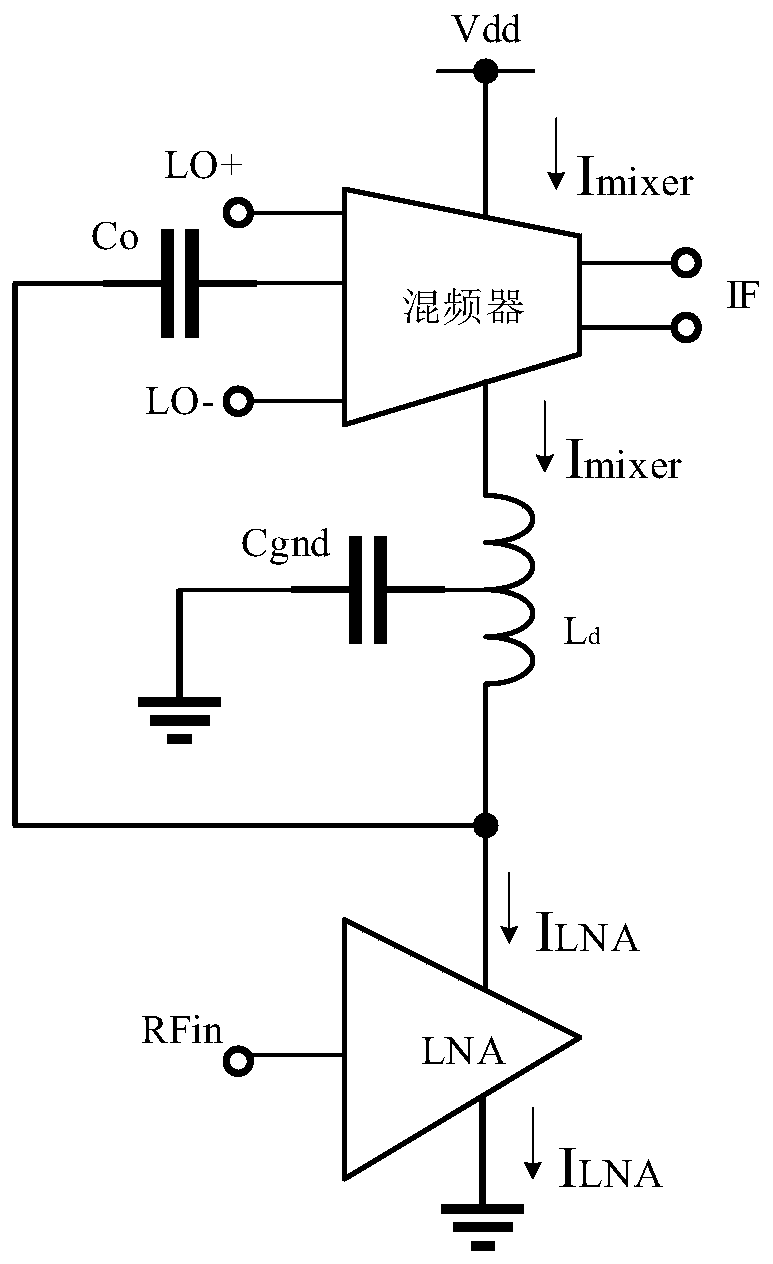
The invention discloses a current multiplexing radio frequency front end structure, and belongs to the technical field of electronic circuits. The current multiplexing radio frequency front end structure comprises a mixer, a low noise amplifier and a static bias current control circuit, the signal output end of the low-noise amplifier is connected with the signal input end of the frequency mixer;the low-noise amplifier and the frequency mixer realize static bias current sharing through a three-terminal inductor; a static bias current control circuit is connected between the power supply voltage and the third end of the three-end inductor, and the static bias current control circuit is used for increasing the current flowing to the low-noise amplifier; the static bias current control circuit comprises a PMOS transistor, a source electrode and a grid electrode of the PMOS transistor are connected, the source electrode of the PMOS transistor is connected with power supply voltage, and adrain electrode of the PMOS transistor is connected with the third end of the three-end inductor; the problem that an existing radio frequency front end structure is large in power consumption is solved. And the effects of reducing the power consumption of the radio frequency front-end structure and realizing the low-power-consumption application of the wireless sensor network are achieved.

Description

technical field [0001] The present application relates to the technical field of electronic circuits, in particular to a current multiplexed radio frequency front-end structure. Background technique [0002] With the development of Internet of Things technology, the application of wireless sensor network technology is becoming more and more extensive. In some application scenarios, there are high requirements on the service life of the wireless sensor network system, such as 10 years. In order to meet the higher system life requirements, the terminal equipment in the wireless sensor network system also needs a higher battery life correspondingly. As the core power consumption unit in the wireless sensor network, the RF front-end structure directly affects the overall power consumption of the wireless sensor network system. [0003] The RF front-end structure generally includes low-noise amplifiers and mixers, such as figure 1 As shown, in the traditional RF front-end stru...

Claims


Application Information

Patent Timeline
Patent Type & Authority Applications(China)
IPC IPC(8): H04W52/02H04B1/40
CPCH04W52/0209H04B1/40Y02D30/70
Inventor 戴若凡
Owner SHANGHAI HUAHONG GRACE SEMICON MFG CORP
Learn More