
A kind of antenna device and electronic equipment

A technology of antenna device and electronic equipment, which is applied in the field of communication, can solve problems such as poor antenna performance, and achieve the effect of thinning and thinning

Active Publication Date: 2019-01-29
VIVO MOBILE COMM CO LTD
View PDF5 Cites 0 Cited by
  • Summary
  • Abstract
  • Description
  • Claims
  • Application Information

AI Technical Summary

Problems solved by technology

[0003] The embodiment of the present invention provides an antenna device and electronic equipment to solve the problems of the antenna and other electronic components interacting with each other and the performance of the antenna is poor in the prior art electronic equipment

Method used


Image

  • A kind of antenna device and electronic equipment
  • A kind of antenna device and electronic equipment
  • A kind of antenna device and electronic equipment

Examples


no. 1 example

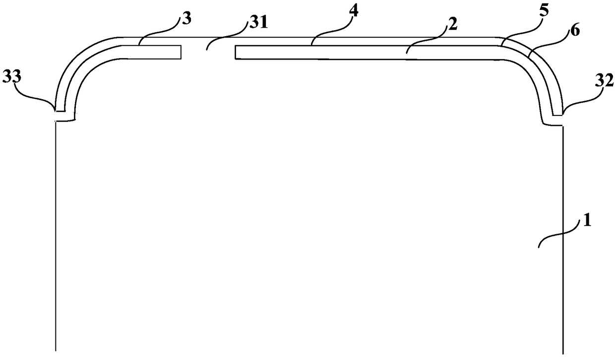
[0023] Such as figure 1 As shown, the embodiment of the present invention provides an antenna device, which is applied to an electronic device. The electronic device includes a metal battery cover 1 and a plastic support structure 2. The antenna device specifically includes: a slot antenna body 3, a first tuner part 4, the second tuning part 5 and the feeding part 6.

[0024] Wherein, the metal battery cover 1 has a slit structure, and the plastic support structure 2 is located in the slit structure, which not only shields the slit structure from being exposed to the outside of the metal battery cover 1, but also makes the metal battery cover 1 as a whole flat or curved surface. , without bumps and depressions on the surface. Further, the slot antenna body 3 of the antenna device is formed along the first edge where the metal battery cover 1 is in contact with the top surface of the plastic support structure 2, and a connecting portion 31 is provided on the metal battery cove...

no. 2 example

[0029] The above first embodiment briefly introduces the antenna device of the present invention, and the following embodiment will further describe it in conjunction with the accompanying drawings and specific application scenarios.

[0030] Such as Figure 1 to Figure 4 As shown, the antenna device of the embodiment of the present invention is applied to an electronic device, and the electronic device includes a metal battery cover 1 with a slit structure, a plastic support structure 2 located in the slit structure, and the plastic support structure 2 shields the slit structure It is not exposed outside the metal battery cover 1 , and the outer surface of the metal battery cover 1 is guaranteed to be flat or arc-shaped, without protrusions or depressions.

[0031] Specifically, the antenna device includes: a slot antenna body 3 , a first tuning part 4 , a second tuning part 5 and a feeding part 6 . Wherein, the slot antenna body 3 is formed along the first edge where the me...

no. 3 example

[0039] The third embodiment of the present invention also provides an electronic device, the electronic device includes a metal battery cover with a gap structure, a plastic support structure located in the gap structure, and as described in the first embodiment and the second embodiment Antenna device described above.

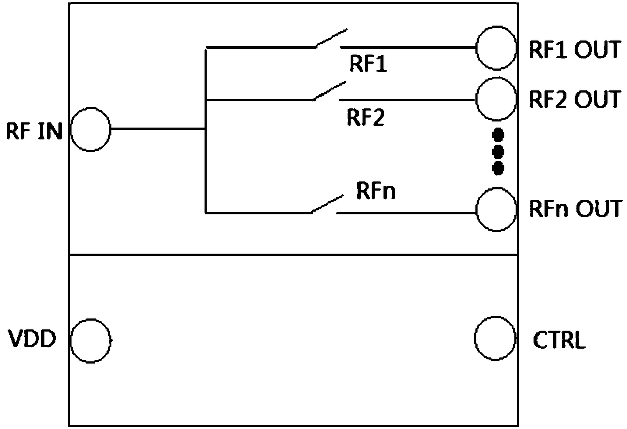
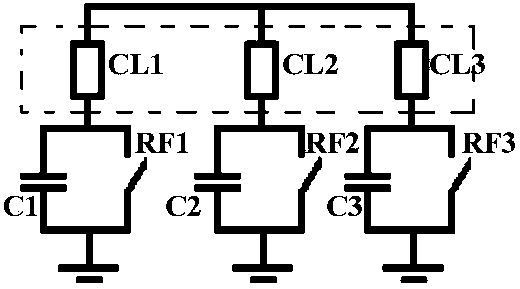
[0040] The electronic equipment sets the antenna device as a segmented slot antenna, and sets a first tuning part and a second tuning part on the side where the feeding part is located. circuit and the second switch matching circuit to ensure the radio frequency performance of each frequency band. In addition, due to the use of the slot antenna, more space can be provided for the arrangement of other electronic components, meeting the user's demand for thinner and lighter electronic equipment.


PUM


Abstract

The invention discloses an antenna device and an electronic device. The electronic device comprises a metal cell cover with a slit structure, and a plastic support structure arranged in the slit structure. The antenna device comprises a slit antenna body formed by being along a first edge, in contact with the top end face of the plastic support structure, of the metal cell cover. A connection part is arranged on the metal cell cover to divide the slit antenna body into two segments. The slit antenna body is short circuited with a grounding end through the connection part. The antenna device also comprises a first tuning part, a second tuning part and a feed part which are successively arranged between the connection part and the first end of the slit antenna body. The first tuning part is connected with the grounding end through a first switch matching circuit. The second tuning part is connected with the grounding end through a second switch matching circuit. The feed part is connected with a radio frequency front end through a spring sheet or a flexible circuit board. According to the invention, when multi-band reuse is achieved, radio frequency performance of each brand and light and thin performance of the electronic device can be ensured.

Description

technical field [0001] The invention relates to the technical field of communications, in particular to an antenna device and electronic equipment. Background technique [0002] With the rapid development of mobile terminals, mobile terminals with metal texture will continue to be popular in the future. Faced with various metal structures, the antenna signal of electronic equipment has become a challenge for the industry. In addition, in order to meet users' requirements for thinner and lighter appearance of electronic equipment, the layout space of other electronic components of the electronic equipment is very limited, causing the layout of conductive components to affect the performance of the antenna. Contents of the invention [0003] Embodiments of the present invention provide an antenna device and electronic equipment, so as to solve the problems in the prior art of electronic equipment that the antenna interacts with other electronic components and the performanc...

Claims


Application Information

Patent Timeline
Patent Type & Authority Patents(China)
IPC IPC(8): H01Q5/328H01Q5/10H01Q5/20H01Q1/44H01Q13/10
CPCH01Q1/44H01Q5/10H01Q5/20H01Q5/328H01Q13/10
Inventor 张声陆
Owner VIVO MOBILE COMM CO LTD
Learn More