Unlock instant, AI-driven research and patent intelligence for your innovation.

Turbocharger with predetermined breaking point for an internal combustion engine

A turbocharger and fractured part technology, applied in internal combustion piston engines, mechanical equipment, combustion engines, etc., can solve problems such as escape, and achieve the effect of reducing oil loss

Active Publication Date: 2019-12-27
VTESCO TECH GMBH
View PDF5 Cites 0 Cited by
  • Summary
  • Abstract
  • Description
  • Claims
  • Application Information

AI Technical Summary

Problems solved by technology

This can especially have the disadvantageous consequence that oil can escape into the exhaust gas region in such an amount that the internal combustion engine has to be switched off directly, the turbocharger being coupled into the oil circuit of the internal combustion engine in order to avoid, for example, the exhaust gas aftertreatment system even greater collateral damage

Method used


Image

  • Turbocharger with predetermined breaking point for an internal combustion engine
  • Turbocharger with predetermined breaking point for an internal combustion engine
  • Turbocharger with predetermined breaking point for an internal combustion engine

Examples


Embodiment Construction

[0044] figure 1 and figure 2 This relates to the known prior art and has already been described at the outset in order to explain the structure of a conventional turbocharger and corresponding exemplary embodiments of the associated turbocharger rotor.

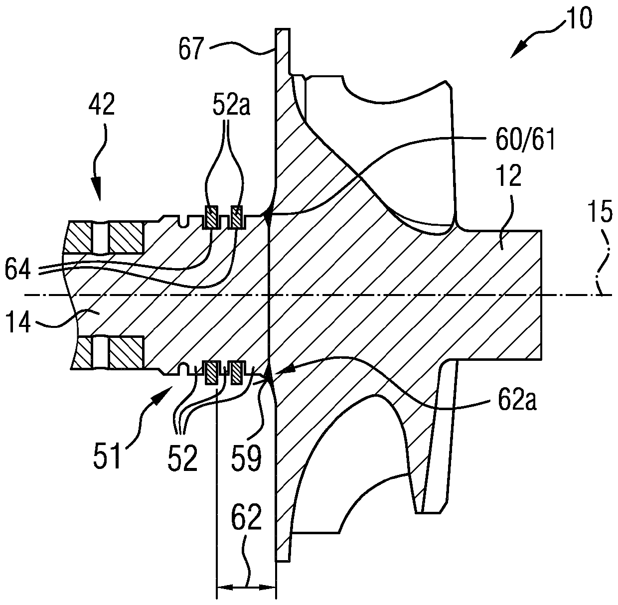
[0045] according to image 3 and 4 Two exemplary embodiments of a turbocharger 1 are described, in which according to the invention a predetermined breaking point 61 is provided on the turbocharger rotor 10 at the radial bearing 42 of the turbocharger 1 In the event of a failure or other overloading of the turbocharger rotor 10 , a targeted breaking of the rotor shaft 14 at this predetermined breaking point 61 is achieved.

[0046] image 3 It relates to a first embodiment of a turbocharger 1 which essentially corresponds, for example, according to figure 1 and 2 A turbocharger 1 with a turbocharger rotor 10. exist image 3 Only a section of the turbocharger rotor 10 is schematically shown in section, which highlights...


PUM


Abstract

The invention relates to a turbocharger (1) for an internal combustion engine, comprising a bearing housing (41) in which a turbocharger rotor (10) is mounted in a rotatable manner about the rotor rotational axis (15) of the rotor shaft (14). A turbine wheel (12) is rotationally fixed on the rotor shaft (14) and is arranged in a turbine housing (21) secured to the bearing housing (41). An oil sealis arranged between the rotor shaft (14) and the bearing housing (41), between the turbine wheel (12) and a radial bearing (42) paired with the turbine wheel (12), in order to seal the bearing housing (41) from the turbine housing (21). Advantageously, a predetermined breaking point (61) is formed for the turbocharger rotor (10) of the turbocharger (1), said breaking point lying in a breaking point region (62) which extends axially between the turbine wheel back (67) and a rotor shaft oil seal (51) axial end (53) facing the turbine wheel back.

Description

technical field [0001] The invention relates to a turbocharger for an internal combustion engine, which has a predetermined breaking point on the turbocharger rotor. Background technique [0002] Exhaust gas turbochargers are increasingly used to increase the performance of internal combustion engines in motor vehicles. This is happening more and more frequently with the aim of reducing the structural size and weight of internal combustion engines at the same or even increased power and at the same time reducing consumption and thus reducing CO 2 emission. The principle of action is that the energy contained in the exhaust gas flow is used to increase the pressure in the intake line of the internal combustion engine and thus achieve an improved filling of the combustion chamber of the internal combustion engine with air-oxygen. As a result, more fuel, such as gasoline or diesel, can be converted per combustion process, which increases the power of the internal combustion ...

Claims


Application Information

Patent Timeline
Patent Type & Authority Applications(China)
IPC IPC(8): F02C6/12
CPCF05D2230/238F01D5/025F01D5/026F01D21/04F01D21/10F02C6/12F05D2220/40F05D2230/237F02C7/06F02C7/28Y02T10/12F02B39/16
Inventor R.伯宁M.克劳斯D.弗兰肯斯坦B.莱迈尔B.费尔林
Owner VTESCO TECH GMBH