
Coiling machine coiling shaft sleeve feeding device suitable for different specifications of sleeves

A sleeve and roll technology, applied in the field of sleeve device on the reel of the coiler, can solve the problems of not being able to clamp sleeves of various specifications, clamping sleeve size limitation, low degree of automation, etc., and achieve good promotion Application value, easy operation and high degree of automation

Pending Publication Date: 2019-12-31
CHINA ALUMINUM INT ENG CORP +1
View PDF0 Cites 1 Cited by
  • Summary
  • Abstract
  • Description
  • Claims
  • Application Information

AI Technical Summary

Problems solved by technology

The upper sleeve device in the prior art has the following disadvantages: long operating time, low work efficiency, and low degree of automation; generally only for one type of sleeve, there is a limit to the size of the clamping sleeve, and it cannot be clamped. Take sleeves of various specifications

Method used


Image

  • Coiling machine coiling shaft sleeve feeding device suitable for different specifications of sleeves
  • Coiling machine coiling shaft sleeve feeding device suitable for different specifications of sleeves

Examples


Embodiment Construction

[0013] The technical solution of the present invention will be described in further detail below in conjunction with the accompanying drawings and embodiments.

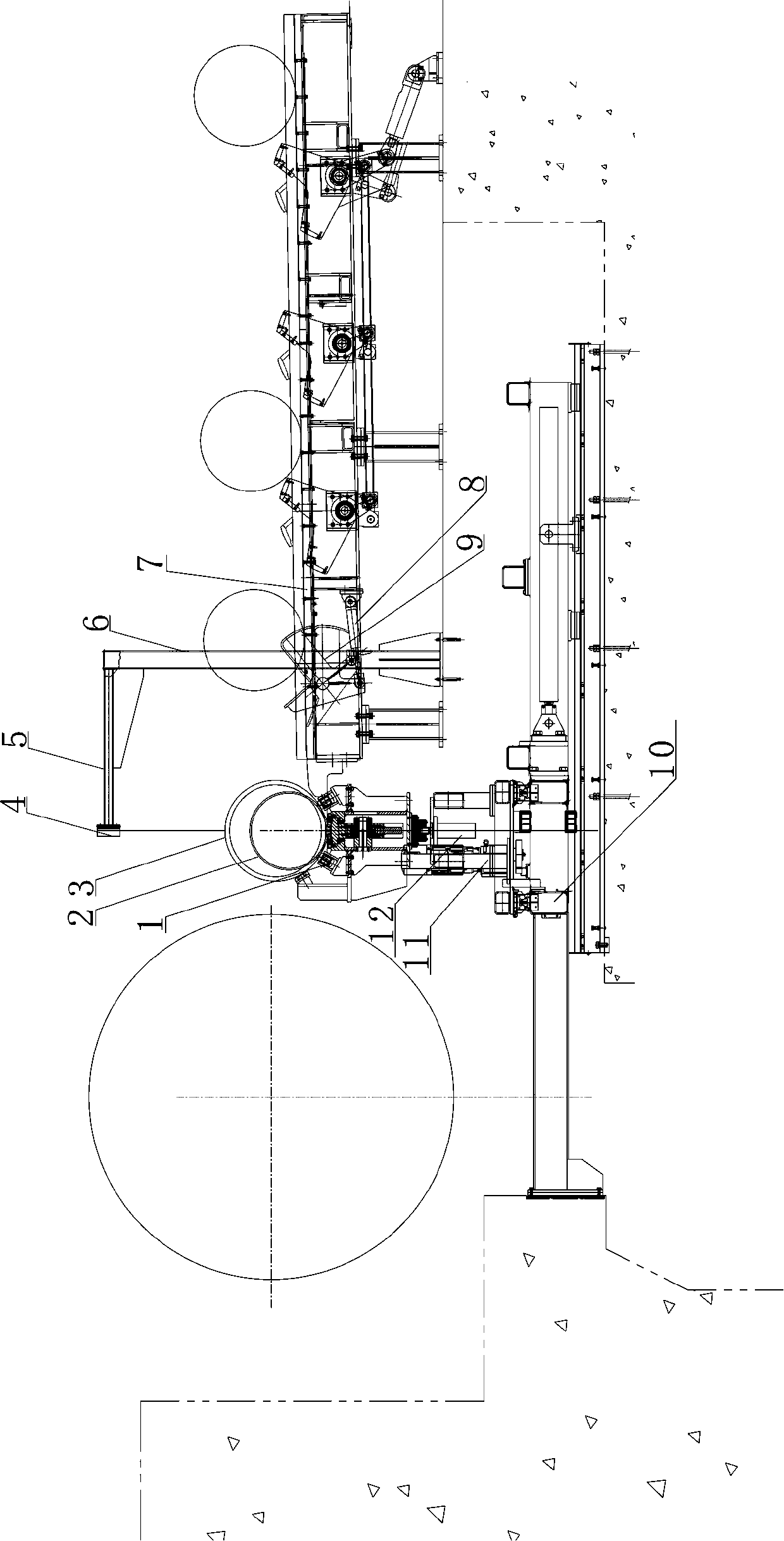
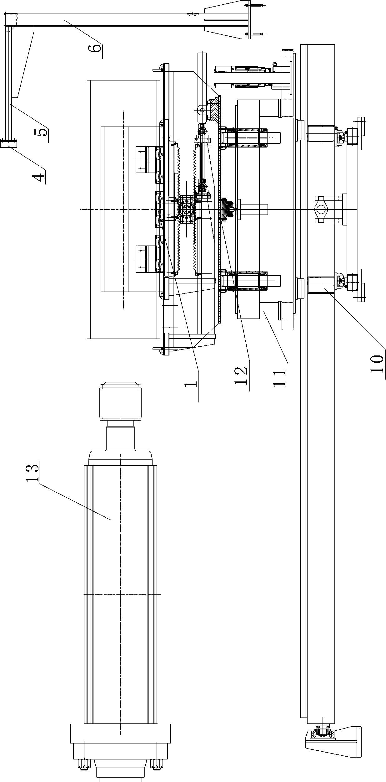
[0014] like figure 1 As shown, the sleeve device on the reel of the coiler suitable for sleeves of different specifications includes a sleeve storage rack 7, a centering device 1, a bracket device 12, a longitudinal moving device 11 and a lateral moving device 10. The sleeve storage rack 7 is inclined in the horizontal direction, and the inclination angle is 1 ° to 5 °. The head end height of the sleeve storage rack is lower than the tail end height; the sleeve storage rack is provided with several Fork device, each fork device is composed of fork assemblies symmetrically located on both sides of the sleeve storage rack, the fork assembly includes a fork cylinder 8 and a fork body 9, and the fork cylinder is installed on the sleeve storage rack 7, The piston rod of the shift fork oil cylinder is connected with the sh...


PUM


Abstract

The invention discloses a coiling machine coiling shaft sleeve feeding device suitable for different specifications of sleeves. The coiling machine coiling shaft sleeve feeding device comprises a sleeve storage rack, a centering device, a bracket device, a longitudinal moving device and a transverse moving device. The sleeve storage rack is inclined at the inclined angle of 1 degree-5 degrees in the horizontal direction. The head end of the sleeve storage rack is lower than the tail end of the sleeve storage rack. The sleeve storage rack is provided with a plurality of shifting fork devices atintervals in the length direction of the sleeve storage rack. The longitudinal moving device is mounted on the transverse moving device. The bracket device is slidably mounted on the longitudinal moving device. The centering device is mounted on a bracket of the bracket device. The head end of the sleeve storage rack is arranged close to the centering device. The coiling machine coiling shaft sleeve feeding device can achieve the sleeve feeding effect on two or more kinds of sleeves and is accurate in place and high in automation degree.

Description

technical field [0001] The invention relates to the technical field of metallurgical equipment, in particular to a sleeve device on a reel of a coiler suitable for sleeves of different specifications. Background technique [0002] In the field of metallurgical equipment, especially in the field of non-ferrous metal processing equipment, it is necessary to put sleeves of different sizes on the reel of the coiler in order to manufacture finished products with different coil widths and coil inner diameters. The upper sleeve device in the prior art has the following disadvantages: long operating time, low work efficiency, and low degree of automation; generally only for one type of sleeve, there is a limit to the size of the clamping sleeve, and it cannot be clamped. Get sleeves of various specifications. Contents of the invention [0003] In order to solve the above problems, the object of the present invention is to provide a sleeve device on the reel of a coiler suitable f...

Claims


Application Information

Patent Timeline
Patent Type & Authority Applications(China)
IPC IPC(8): B21C47/24
CPCB21C47/24
Inventor 南江鹏常远李广杰
Owner CHINA ALUMINUM INT ENG CORP
Learn More