Cutting device for log machining

A cutting device and log technology, which is applied to wood processing equipment, manufacturing tools, forming/shaping machines, etc., can solve the problems of physical injury of workers, inability to cut to fixed lengths, and no dust reduction effect, etc., so as to improve cutting efficiency, Ensure stability and avoid waste

Inactive Publication Date: 2019-12-31
湖北华诺木业有限公司
View PDF0 Cites 5 Cited by
  • Summary
  • Abstract
  • Description
  • Claims
  • Application Information

AI Technical Summary

Problems solved by technology

[0003] In the process of log processing, it needs to be cut. The general cutting device only has the function of cutting, and cannot perform fixed-length cutting, which cannot meet people's production needs.
At the same time, a large amount of dust will be generated during the cutting process of the log, and the general cutting device does not have the effect of reducing dust, which will cause harm to the body of the staff in the long run

Method used


Image

  • Cutting device for log machining
  • Cutting device for log machining
  • Cutting device for log machining

Examples


Embodiment 1

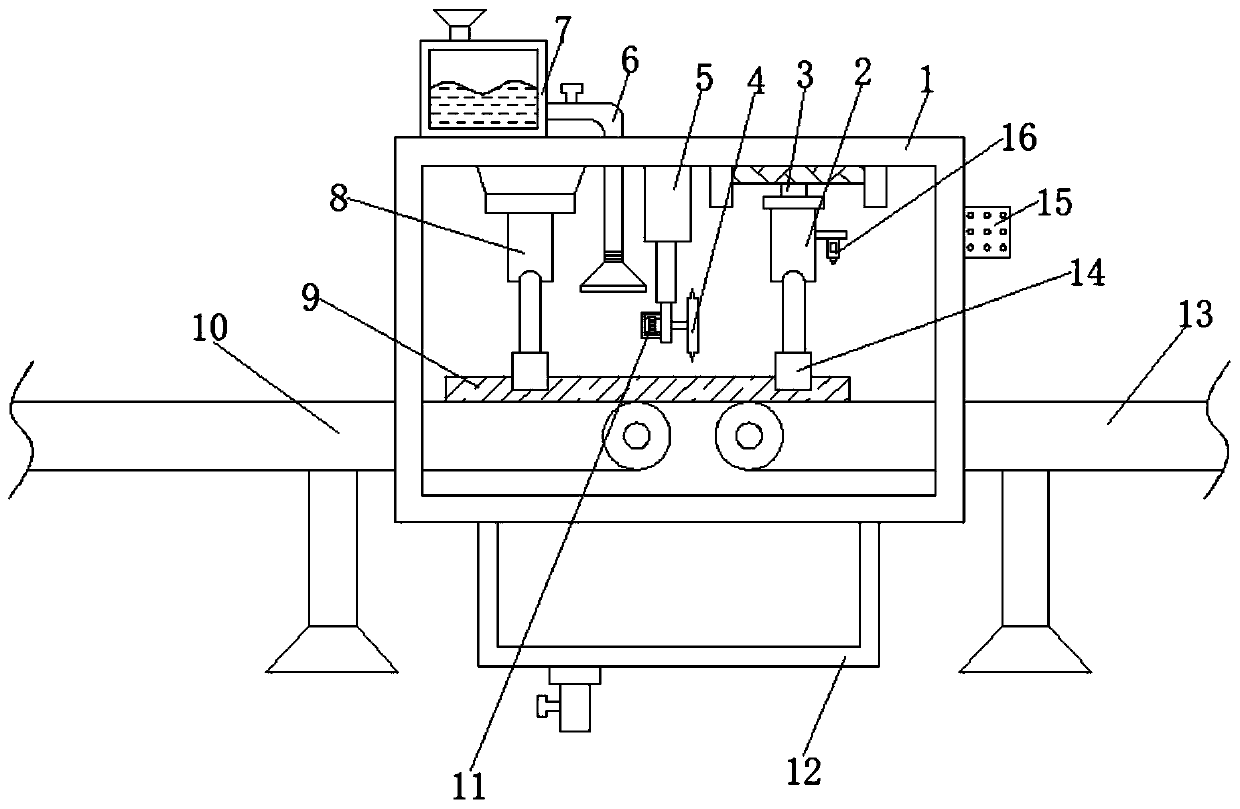
[0026] refer to Figure 1-2 , a cutting device for log processing, including a box body 1, a first conveyor belt 10 and a second conveyor belt 13, the top inner wall of the box body 1 is connected with a second electric push rod 5 by bolts, and one end of the second electric push rod 5 The outer wall is connected with a fixed plate, the outer wall of one side of the fixed plate is connected with the protective shell 11 by bolts, and the inner wall of one side of the protective shell 11 is connected with the motor by bolts, and the outer wall of one end of the output shaft of the motor is welded with the cutting wheel 4, the box body 1 The top outer wall of the tank is connected with a liquid storage tank 7 by bolts, and a connecting pipe 6 is plugged into one side of the liquid storage tank 7, and one end of the connecting pipe 6 extends to the inside of the box body 1, and one end of the connecting pipe 6 is threaded on the outer wall. Atomizing nozzle.

[0027] Wherein, the...

Embodiment 2

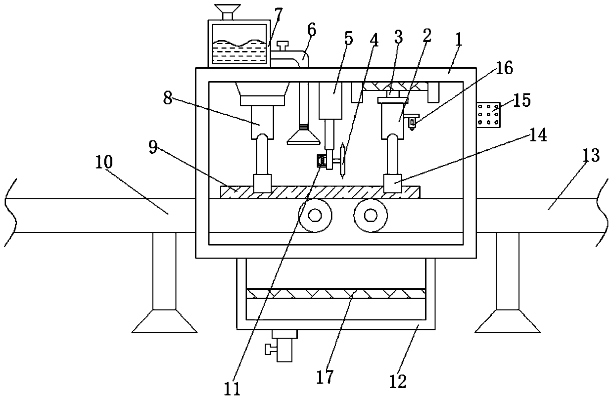
[0030] refer to image 3 , a cutting device for log processing. Compared with Embodiment 1 in this embodiment, the inner walls on both sides of the material storage box 12 are connected with filter screens 17 by bolts.

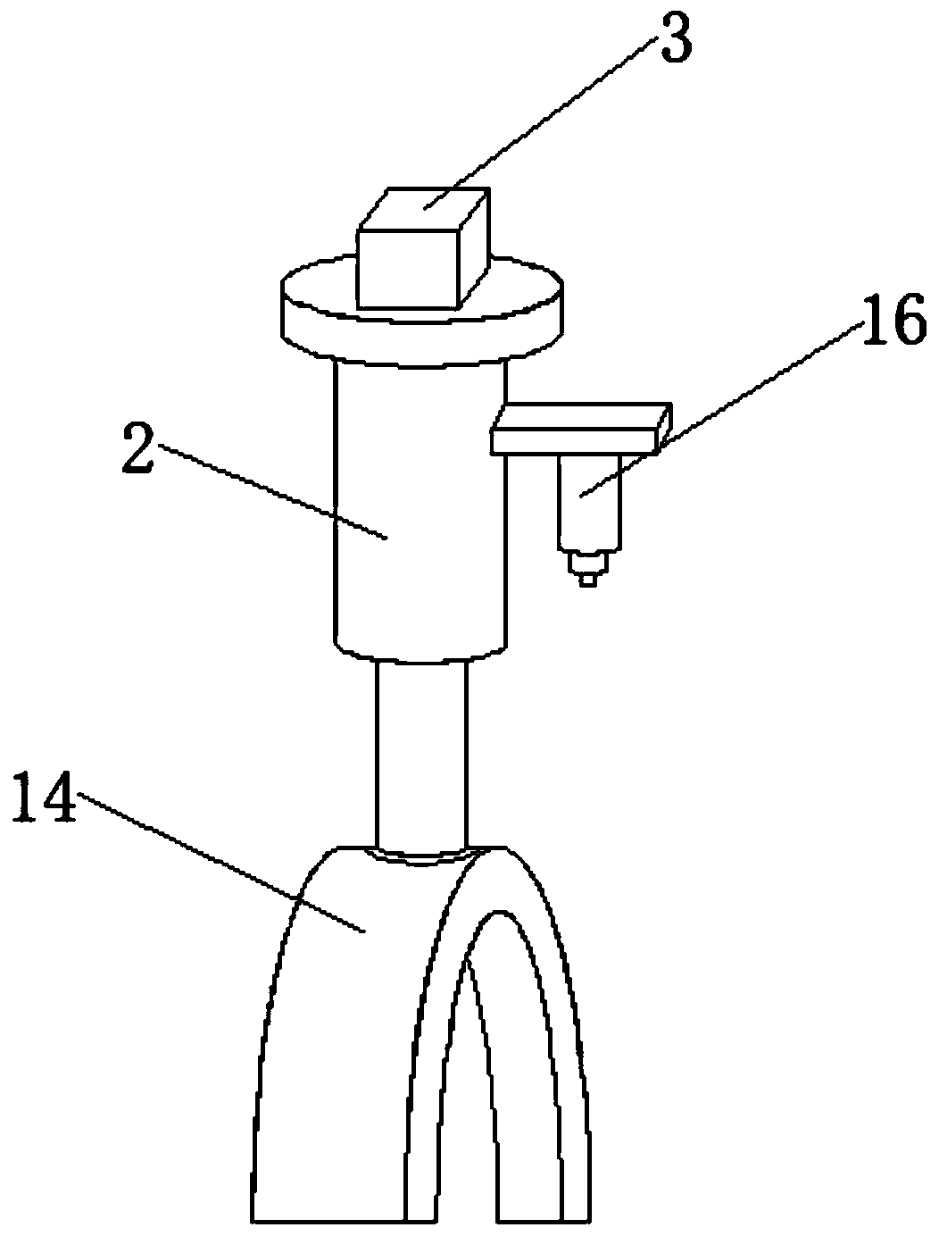
[0031] Working principle: when in use, the staff places the wood body 9 on the first conveyor belt 10, and with the conveyance of the first conveyor belt 10, when the wood body 9 moves to the right below the infrared sensor 16, the first conveyor belt 10 and the second The conveyor belt 13 stops working, and the first electric push rod 2, the second electric push rod 5 and the third electric push rod 8 start working simultaneously, and the second electric push rod 5 drives the cutting wheel 4 to cut the timber body 9, and the first The electric push rod 2 and the third electric push rod 8 drive the fixing ring 14 to move down and can effectively fix the timber body 9, which ensures the stability of the cutting work and improves the cutting efficiency of the de...


PUM


Abstract

The invention discloses a cutting device for log machining. The device comprises a box body, a first conveyor belt and a second conveyor belt, wherein a second electric push rod is arranged on the inner wall of the top of the box body, a fixing plate is connected to the outer wall of one end of the second electric push rod, a protective shell is arranged on the outer wall of one side of the fixingplate, a motor is arranged on the inner wall of one side of the protective shell, a cutting wheel is arranged on the outer wall of one end of a motor output shaft, a liquid storage box is arranged onthe outer wall of the top of the box body, a connecting pipe is inserted into the outer wall of one side of the liquid storage box, one end of the connecting pipe extends into the box body, and an atomizing nozzle is in threaded connection with the outer wall of one end of the connecting pipe. According to the device, when the cutting wheel cuts a log, a first electric push rod and a third electric push rod are started, the first electric push rod and the third electric push rod drive a fixing ring to move downwards, a wood body can be effectively fixed, the cutting work stability is guaranteed, and the cutting efficiency of the device is improved.

Description

technical field [0001] The invention relates to the technical field of log processing, in particular to a cutting device for log processing. Background technique [0002] Wood is a lignified tissue formed by plants capable of secondary growth, such as trees and shrubs, and a log is a wood segment that is cut into a certain length according to the size, shape, and quality standards or special regulations. The segments are called logs. [0003] During the processing of log, it needs to be cut. The general cutting device only has the function of cutting, and cannot perform fixed-length cutting, which cannot meet people's production needs. At the same time, a large amount of dust will be produced during the cutting process of the log by the device. The general cutting device does not have a dust-reducing effect, which will cause harm to the health of the staff in the long run. Therefore, a cutting device for log processing is urgently needed to solve the above problems. Cont...

Claims


Application Information

Patent Timeline
Patent Type & Authority Applications(China)
IPC IPC(8): B27C5/00B27C5/06B27G3/00
CPCB27C5/00B27C5/06B27G3/00
Inventor 敖红才
Owner 湖北华诺木业有限公司
Why Eureka
Try Eureka