Control system for automatically controlling water intake and water drainage of water sink
A control system, water inlet and drainage technology, applied in the field of kitchen and bathroom, can solve the problems of inconvenient control, inconvenient operation, cumbersome control, etc., and achieve the effect of automatic drainage, convenient operation and saving control space
- Summary
- Abstract
- Description
- Claims
- Application Information
AI Technical Summary
Problems solved by technology
Method used
Image
Examples
Embodiment 1
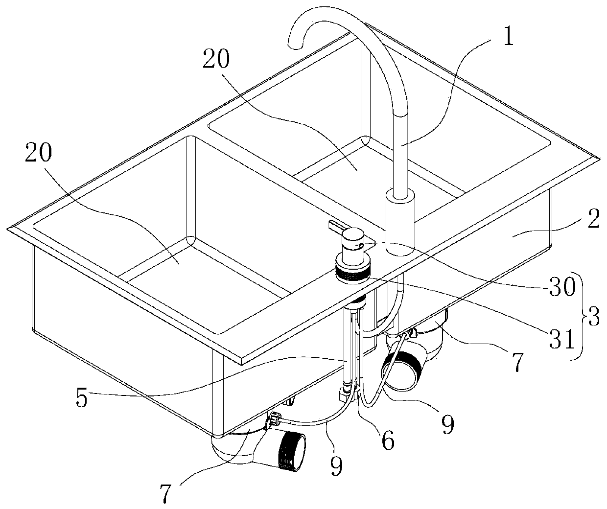
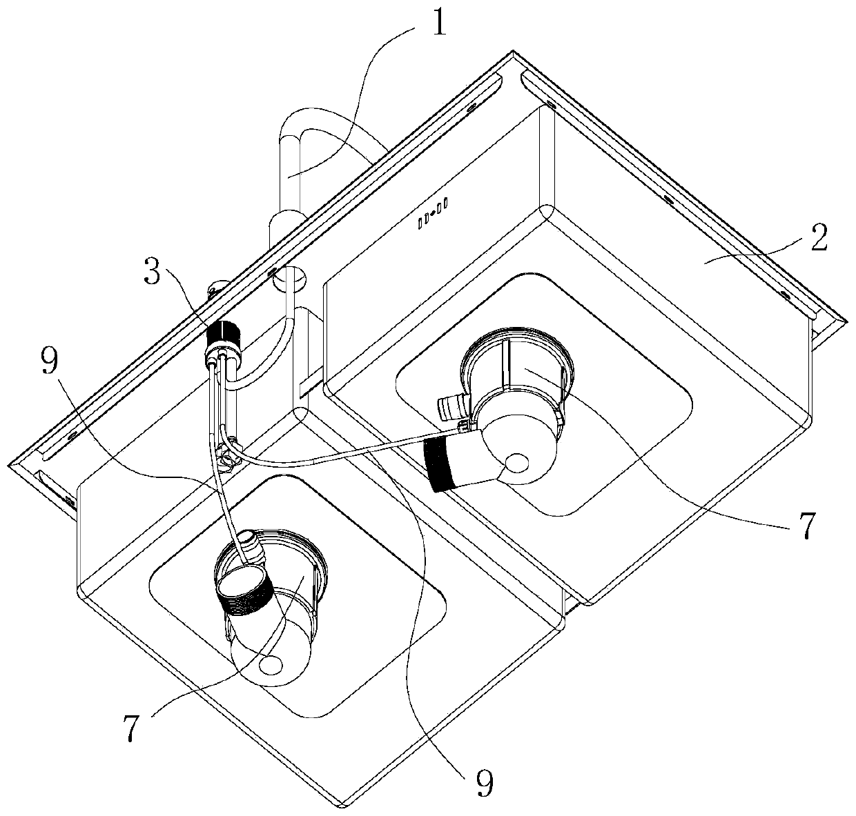
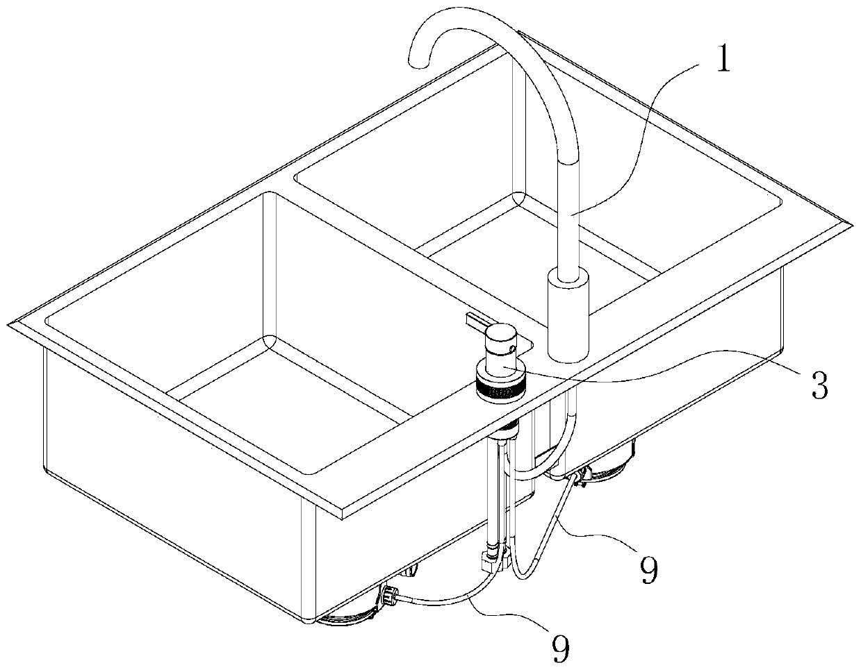
[0055] A control system for automatically controlling the water intake and drainage of the tank, such as Figure 1 to Figure 12 As shown, it includes a faucet 1, a sink body 2 and a switch control part 3. The sink body 2 is provided with two cavities 20 for storing water, and the bottom of each cavity 20 on the sink body 2 is provided with a drain for drainage. The drain port 4 and the switch control part 3 are installed on the sink body 2 and control the closing and opening of the hot water inlet pipe 5 and the cold water inlet pipe 6 to supply water to the faucet 1; A cavity for water storage. The bottom of the upper cavity of the sink body is provided with a drain for drainage. The switch control part is installed on the sink body and controls the hot water inlet pipe or cold water inlet pipe, or a single water source to supply water to the faucet. Close and open.
[0056] like Figure 1 to Figure 10 As shown, the water outlet 4 of each cavity 20 on the sink body 2 is als...
Embodiment 2
[0064] like Figure 13 to Figure 17 As shown, the difference between this embodiment and Embodiment 1 is that the launching control switch 31 includes an upper handle launching switch knob 310', a lower handle launching switch knob 311', an upper guiding sliding sleeve 312', a lower guiding sliding sleeve 313', the upper handle lift rod 314' and the lower handle lift rod 315', the valve core body 300 is respectively provided with the upper handle lift rod 314' and the lower handle lift rod 315' to slide along the axial direction. Matching guide hole 3000; the top of the upper handle lifting pull rod 314' is respectively connected with the upper handle thrust rod 3140' protruding from the guide hole in the radial direction of the valve core body 300, and the top of the lower handle lifting pull rod 315' is respectively A lower handle thrust rod 3150' protruding from the guide hole 3000 in the radial direction of the valve core body 300 is connected, and the corresponding valve ...
PUM
 Abstract
Description
Claims
Application Information
 - R&D
- Intellectual Property
- Life Sciences
- Materials
- Tech Scout
- Unparalleled Data Quality
- Higher Quality Content
- 60% Fewer Hallucinations
Browse by: Latest US Patents, China's latest patents, Technical Efficacy Thesaurus, Application Domain, Technology Topic, Popular Technical Reports.
© 2025 PatSnap. All rights reserved.Legal|Privacy policy|Modern Slavery Act Transparency Statement|Sitemap|About US| Contact US: help@patsnap.com


