
Test method of series compensation protection device

A series compensation protection and testing method technology, applied in the field of series compensation protection, can solve the problems of multiple analog acquisition circuits, high spark gap failure rate, and multiple protection functions

Active Publication Date: 2019-12-31
EXTRA HIGH VOLTAGE POWER TRANSMISSION NANJING OF CHINA SOUTHERN POWER GRID
View PDF7 Cites 2 Cited by
  • Summary
  • Abstract
  • Description
  • Claims
  • Application Information

AI Technical Summary

Problems solved by technology

2) There are many analog acquisition circuits and many protection functions
3) The action results of the series compensation protection device have high similarity
[0005] Existing test methods for series compensation protection devices have a high failure rate of spark gaps and are often unreliable in triggering

Method used


Image

  • Test method of series compensation protection device

Examples


Embodiment 1

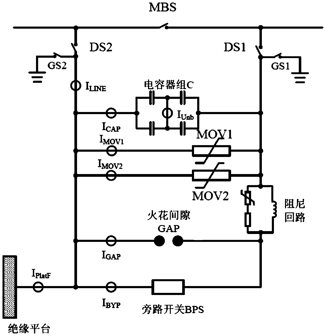
[0109] The invention provides a test method for a series compensation protection device, such as figure 1 As shown, the series compensation protection device includes capacitor bank C, normally open contact GS1, normally open contact DS1, normally open contact GS2, normally open contact DS2, normally open contact MBS, rheostat MOV1, rheostat MOV2, damping circuit, spark gap GAP, bypass switch BPS and insulation platform;

[0110] The capacitor bank C includes a capacitor C1, a capacitor C2, a capacitor C3, and a capacitor C4, the capacitor C1 is connected in series with the capacitor C2, the capacitor C2 is connected in series with the capacitor C3, the capacitor C3 is connected in series with the capacitor C4, and the capacitor C4 is connected in series with the capacitor C1;

[0111] The damping circuit includes a resistor R1, a rheostat R2 and an inductor L, the resistor R1 is connected in series with the rheostat R2, the rheostat R2 is connected in series with the inductor...


PUM


Abstract

The invention discloses a test method of a series compensation protection device. The series compensation protection device comprises a capacitor bank C, a normally open contact GS1, a normally open contact DS1, a normally open contact GS2, a normally open contact DS2, a normally open contact MBS, a rheostat MOV1, a rheostat MOV2, a damping loop, a spark gap GAP, a bypass switch BPS and an insulating platform. The capacitor bank C comprises a capacitor C1, a capacitor C2, a capacitor C3 and a capacitor C4, wherein the capacitor C1 and the capacitor C2 are connected in series, the capacitor C2and the capacitor C3 are connected in series, the capacitor C3 and the capacitor C4 are connected in series, and the capacitor C4 and the capacitor C1 are connected in series. The damping loop comprises a resistor R1, a rheostat R2 and an inductor L, wherein the resistor R1 and the rheostat R2 are connected in series, the rheostat R2 and the inductor L are connected in series, and the inductor L and the resistor R1 are connected in series. According to the series compensation protection device, the triggering reliability of the spark gap is guaranteed, the triggering continuity of the spark gap is guaranteed, the correctness of the action behavior of the spark gap is guaranteed, the triggering reliability is high, the withstand voltage level is high, and the failure rate is low.

Description

technical field [0001] The invention relates to the technical field of series compensation protection, in particular to a testing method for a series compensation protection device. Background technique [0002] The series capacitor compensation technology is to improve the transmission capacity of the line. The capacitor is connected in series to the line. When the high-voltage line fails, the metal oxide arrester (MOV) connected in parallel with the capacitor will act immediately, and at the same time limit the voltage change at both ends of the capacitor. When the accumulated energy of the MOV cannot be dissipated quickly, it will explode and be damaged. Therefore, a spark gap is connected in parallel at both ends of the MOV. When a fault is found, the spark gap will be triggered. Finally, the control system controls the bypass breaker to quickly bypass. Protect capacitors and MOVs. It can be seen that the trigger device of the spark gap is very important, if it cannot b...

Claims


Application Information

Patent Timeline
IPC IPC(8): G01R31/00
CPCG01R31/00
Inventor 苏晓李黄河
Owner EXTRA HIGH VOLTAGE POWER TRANSMISSION NANJING OF CHINA SOUTHERN POWER GRID
Learn More