A fuse device and a load switch fuse assembly cabinet comprising the device

A fuse and installation barrel technology, which is applied in the setting of switch devices, switch devices, emergency protection devices, etc., can solve the problem that the fuse device cannot reliably transmit the trigger force, etc., so as to improve the safety of electricity use, effectively seal, improve The effect of adaptability

Pending Publication Date: 2019-01-18
南京帝开电气自动化有限公司
View PDF0 Cites 0 Cited by
  • Summary
  • Abstract
  • Description
  • Claims
  • Application Information

AI Technical Summary

Problems solved by technology

[0008] The object of the present invention is to provide a fuse device and a load switch fuse combination cabinet including the device, so as to solve the problem that the existing fuse device cannot reliably transmit the triggering force

Method used


Image

  • A fuse device and a load switch fuse assembly cabinet comprising the device
  • A fuse device and a load switch fuse assembly cabinet comprising the device

Examples


Embodiment Construction

[0025] The technical solutions of the present invention will be further described below in conjunction with the accompanying drawings and embodiments. It should be understood that the specific embodiments described here are only used to explain the present invention, but not to limit the present invention. In addition, it should be noted that, for the convenience of description, only the parts related to the present invention are shown in the drawings but not all of them.

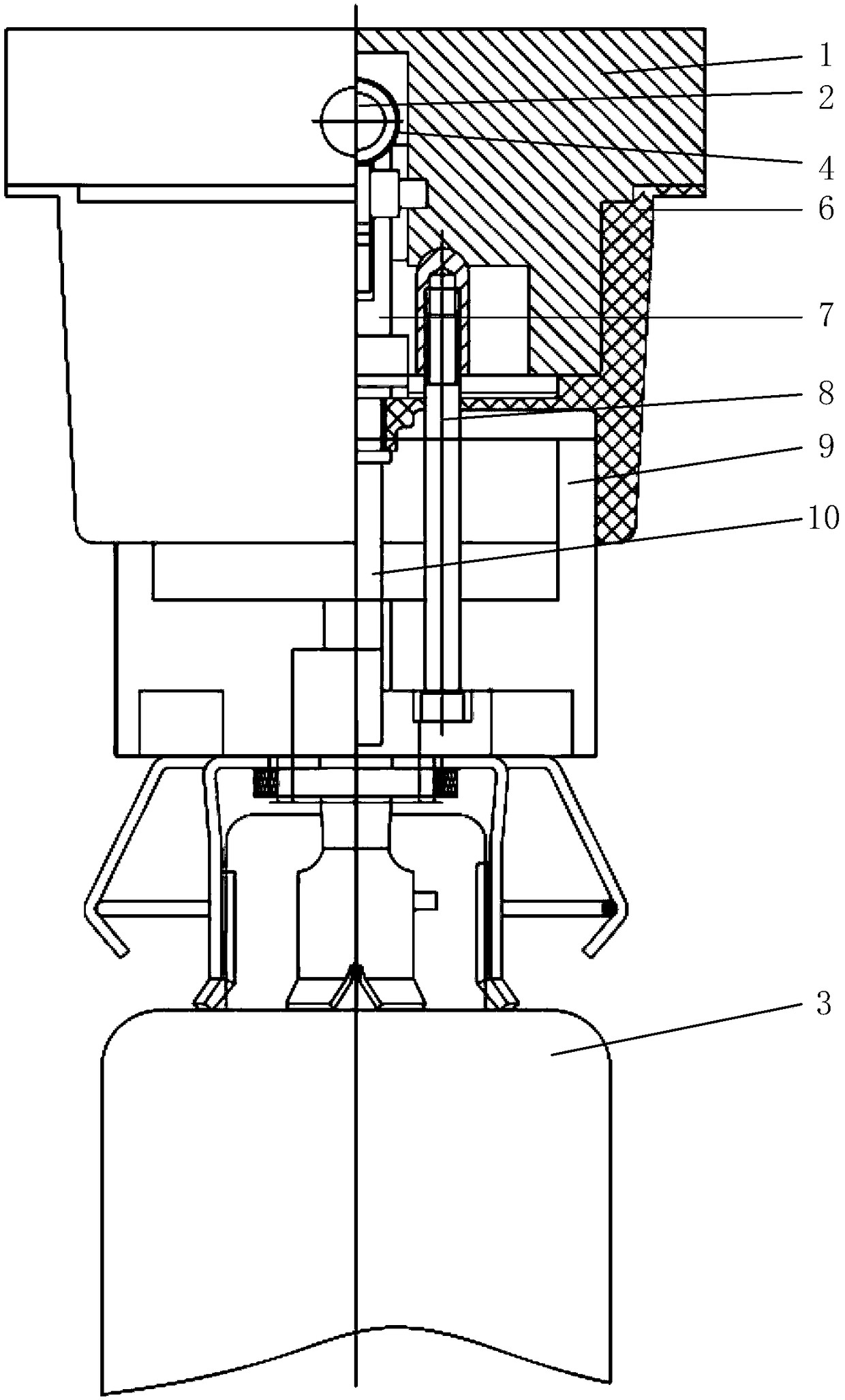
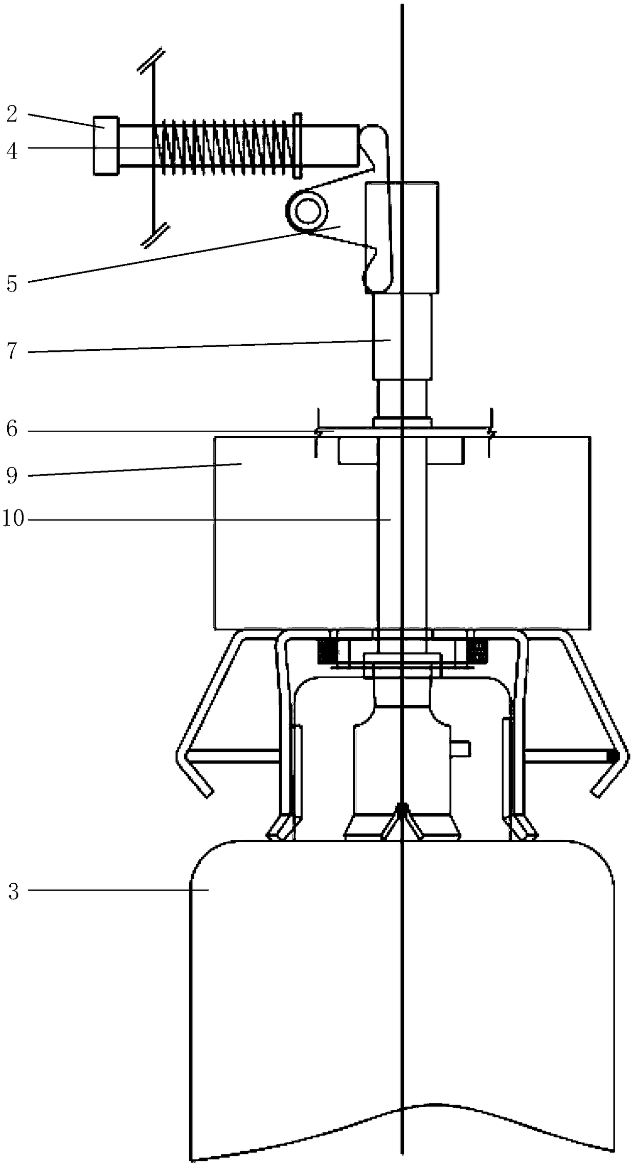
[0026] The invention provides a fuse device, Figure 1-2 Shown is a schematic structural diagram of the fuse device, including an upper end cover 1, a bushing 9, a fuse 3 and a mounting cylinder (not shown in the drawings), and plastic screws 8 pass through and connect the bushing 9, silicon rubber Sleeve and upper end cap1.

[0027] Such as Figure 1-2 As shown, the upper end cover 1 is provided with a push rod 2, a crank arm 5 and a push rod; the push rod 2 is arranged on the upper part of the upper en...


PUM


Abstract

The invention relates to the technical field of power supply, in particular to a fuse device and a load switch fuse assembly cabinet including the device. The fuse device comprises an upper end cover,a bushing, a fuse and a mounting cylinder. An upper end cover is provided with a push rod, a crank arm and a push rod; A push rod is arranged on the upper part of the upper end cover and extends to the outside of the upper end cover; The ejector rod is vertically arranged inside the upper end cover and the bushing; The crank arm is arranged between the push rod and the ejector rod and is articulated with the upper end cover at the articulation point, the ejector rod can push the crank arm to rotate around the articulation point, and the crank arm can push the ejector rod to move; A bushing ispositioned below that upper end cover; A fuse is positioned below the bushing, and an impactor is arranged at the top of the fuse; The mounting cylinder sleeve is arranged on the outside of the bushing and the fuse. By providing a fuse device and a load switch fuse assembly cabinet including the device, the invention can effectively improve the triggering reliability of the system.

Description

technical field [0001] The invention relates to the technical field of power supply, in particular to a fuse device and a load switch fuse combination cabinet including the fuse device. Background technique [0002] In the field of high-voltage switchgear, load switch fuse combination cabinets are widely used. [0003] The load switch fuse combination cabinet includes a load switch, a chain trip mechanism and a fuse device. When the current exceeds the specified value, the fuse in the fuse device will blow the internal fuse with the heat generated by itself, and pop out the striker The chain release mechanism is triggered to finally open the load switch to achieve the purpose of protecting the safety of electricity consumption. [0004] The current fuse device has the following problems: [0005] (1) The trigger force loss is serious, and the trigger force cannot be transmitted reliably. [0006] (2) The moisture-proof effect is poor, which seriously affects the safety of...

Claims


Application Information

Patent Timeline
Patent Type & Authority Applications(China)
IPC IPC(8): H01H85/02H01H85/04H02B13/00H02B1/28H02B1/18
CPCH01H85/02H01H85/04H02B1/18H02B1/28H02B13/00
Inventor 徐金龙
Owner 南京帝开电气自动化有限公司
Why Eureka
Try Eureka