Supercharge Your Innovation With Domain-Expert AI Agents!

Automatic card ejection device

A card-discharging device and automatic technology, applied in the direction of instruments, coin-operated equipment for distributing discrete items, coin-free or similar appliances, etc., can solve the problem of increasing labor costs, inconvenience for card sellers or card issuers, and inability to effectively prevent Issues such as receiving multiple cards at one time for card holders to achieve good application prospects and effective charging

Inactive Publication Date: 2019-12-31
上海巧盒智能科技有限公司
View PDF17 Cites 0 Cited by
  • Summary
  • Abstract
  • Description
  • Claims
  • Application Information

AI Technical Summary

Problems solved by technology

In the known technology at present, no matter whether the user purchases the smart card and the collection card, or the user receives the smart card and the collection card, it is all artificially collected from the card seller or the card issuer, that is to say, the sale or issuance of the card requires manual management. Carry out the issuance of smart cards and collection cards (especially for the issuance of smart cards and collection cards that need to be charged, it needs to be charged by human management; in the area where no payment is required to collect cards, put all the cards together, and the users themselves according to their needs) Receiving a card, although unmanned on-duty can be realized, but it cannot effectively prevent the card holder from receiving multiple cards at a time), which will bring inconvenience to the card seller or card issuer and increase labor costs

Method used


Image

  • Automatic card ejection device
  • Automatic card ejection device
  • Automatic card ejection device

Examples


Embodiment Construction

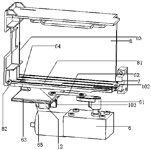
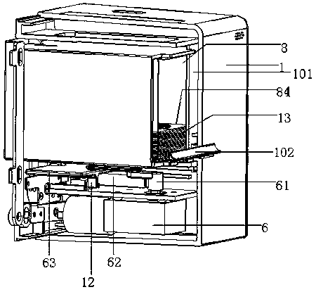
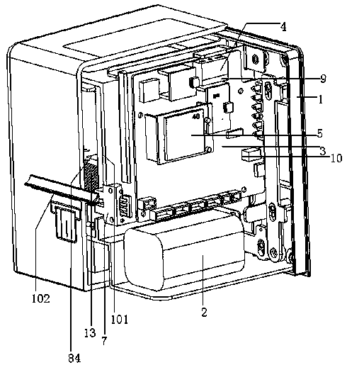
[0020] figure 1 , 2 , 3, 4, 5, and 6, an automatic card issuing device, including a rectangular housing 1, a lithium battery 2, a single-chip-based main control module 3, a code scanner 4, a 4G module 5, and a motor speed reduction mechanism 6 , Infrared sensor 7, card box 8, scanner 4 is equipped with a buzzer 9, a prompt sound will be issued after the scan is successful, the main control module 3 is equipped with a voice module 10, and the middle of the housing has a rectangle from front to back Cavity 101; the code scanner 4 is installed in the upper left front end of the casing 1, the lithium battery 2 is installed in the lower left end of the casing 1, the main control module 3, 4G module 5 are installed on the circuit board, the circuit board Installed in the middle of the left side of the housing 1; the card box 8 is rectangular, the lower end of the card box 8 has an opening slot 81 from the front to the back, and the lower part of the front end of the card box 8 has an ...


PUM


Abstract

The invention provides an automatic card ejection device. The automatic card ejection device comprises a shell, a lithium battery, a main control module, a code scanner, a 4G module, a motor retardingmechanism, an infrared sensor, and a card box, wherein a hollow cavity is formed in the middle of the shell; the code scanner, the lithium battery, the main control module and the 4G module are installed in one side of the shell and are connected with the motor retarding mechanism and the infrared sensor through wires; open slots are formed in the middle of a lower end and in the lower part of afront end of the card box, a key cylinder is arranged at a front lower end of the shell, and the card box is located in the hollow cavity; a card ejection opening is formed in the middle of a rear side end of the shell, the motor retarding mechanism is installed at a lower middle end of the shell, and a rotating arm rod, a connecting rod and a pus rod of the motor retarding mechanism are installedtogether; and a push rod is arranged on the push plate, a microswitch is aranged at an upper end of the shell of the motor retarding mechanism, cards are placed in the card box, and the infrared sensor is installed at the side end of the card ejection opening. The automatic card ejection device provided by the invention realizes unmanned distribution of various smart cards and collection cards, which brings convenience to both card takers and the card issuers, and also enables the card issuers to effectively charge.

Description

Technical field [0001] The invention relates to the field of automation equipment, in particular to an automatic card issuing device. Background technique [0002] With the advancement of technology, there are more and more applications of various smart cards (such as recharge cards, shopping cards, access cards, etc.). At the same time, there are more and more cards with collection functions on the market. In the currently known technology, whether the user purchases the smart card and the collection card, or the user receives the smart card and the collection card, they are collected manually from the card seller or the card issuer, that is to say, the card sales or issuance needs to be managed manually Carry out the issuance of smart cards and collection cards (especially for the issuance of smart cards and collection cards that need to be charged, but also require manual management for charging; in areas where there is no need to pay for the card, put all the cards together, ...

Claims


Application Information

Patent Timeline
IPC IPC(8): G07F17/42
CPCG07F17/42
Inventor 黄海滨
Owner 上海巧盒智能科技有限公司
Features
  • R&D
  • Intellectual Property
  • Life Sciences
  • Materials
  • Tech Scout
  • Unparalleled Data Quality
  • Higher Quality Content
  • 60% Fewer Hallucinations
Learn More