Single spent fuel rod transfer container and using method thereof
A transfer container and spent fuel technology, applied in portable protective containers, nuclear engineering, etc., can solve the problems of time-consuming, pendulum caused by fuel rods, etc., and achieve the effects of easy maintenance, good stability, and avoiding radiation damage
- Summary
- Abstract
- Description
- Claims
- Application Information
AI Technical Summary
Problems solved by technology
Method used
Image

Examples
Embodiment 1
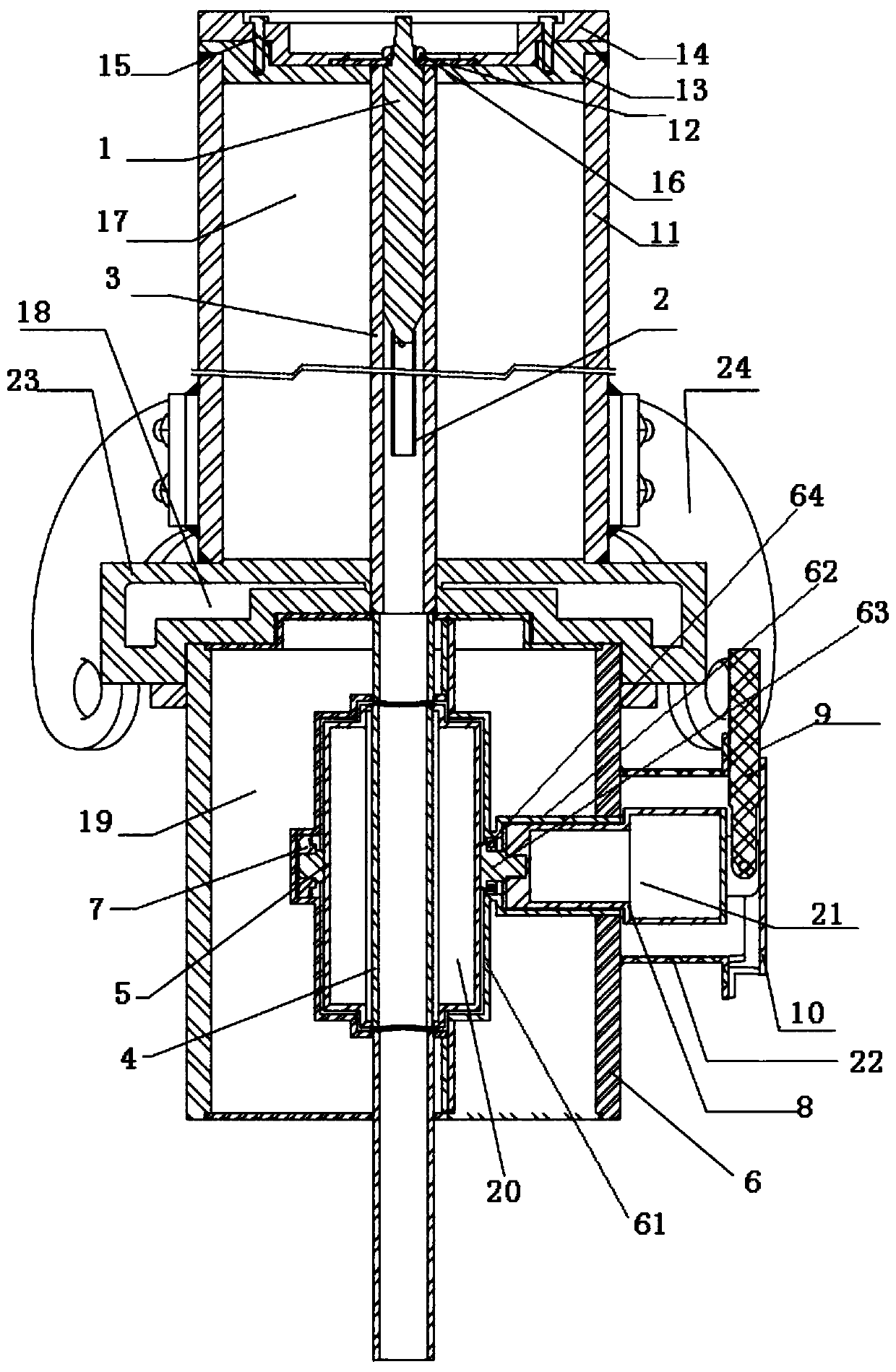
[0042] Such as figure 1 : single spent fuel rod transfer container, including the transfer structure containing spent fuel rods,
[0043] The transfer structure includes a container structure with an open upper end and a lower end, and a rotating device that drives the container structure to rotate,
[0044] It also includes a hoisting structure located above the transfer structure, the hoisting structure includes a dynamic shielding rod 1, the upper end of the dynamic shielding rod 1 is provided with a connecting end that is connected with the push-pull rod, and the lower end of the dynamic shielding rod is connected with a spent fuel rod. connectors;
[0045] Wherein, the rotating device can drive the rotating body of the container structure, so that the opening axes of the upper end and the lower end of the container structure coincide with the axis of the movable shielding rod 1 .
[0046] As can be seen from the above structure, the spatial relationship of the above str...
Embodiment 2
[0048] Such as figure 1 :
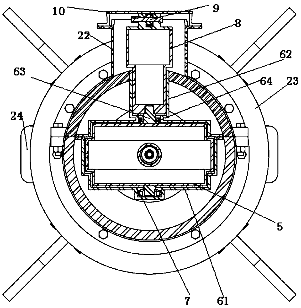
[0049] On the basis of Embodiment 1, specifically, in order to realize the cooperation between the container structure and the rotating device, so that the container structure can complete the rotation under the drive of the rotating device, the present invention borrows the design concept of the valve core, and the shielding valve core 5 and The rotating device is connected, and the drive of the rotating device can freely rotate in the shielding valve core housing 61. Therefore, the container structure includes the shielding valve core 5 and the shielding valve core tube 4 that runs through the shielding valve core and has an open upper end and a lower end. , the shielding spool 5 is covered with a shielding spool housing 61, the shielding spool housing 61 is provided with a bearing hole, and a bearing is arranged in the bearing hole (the symmetrical position of the bearing is provided with a bearing A7), and the bearing seat 64 of the bearing is e...
Embodiment 3
[0056] Such as figure 1 :
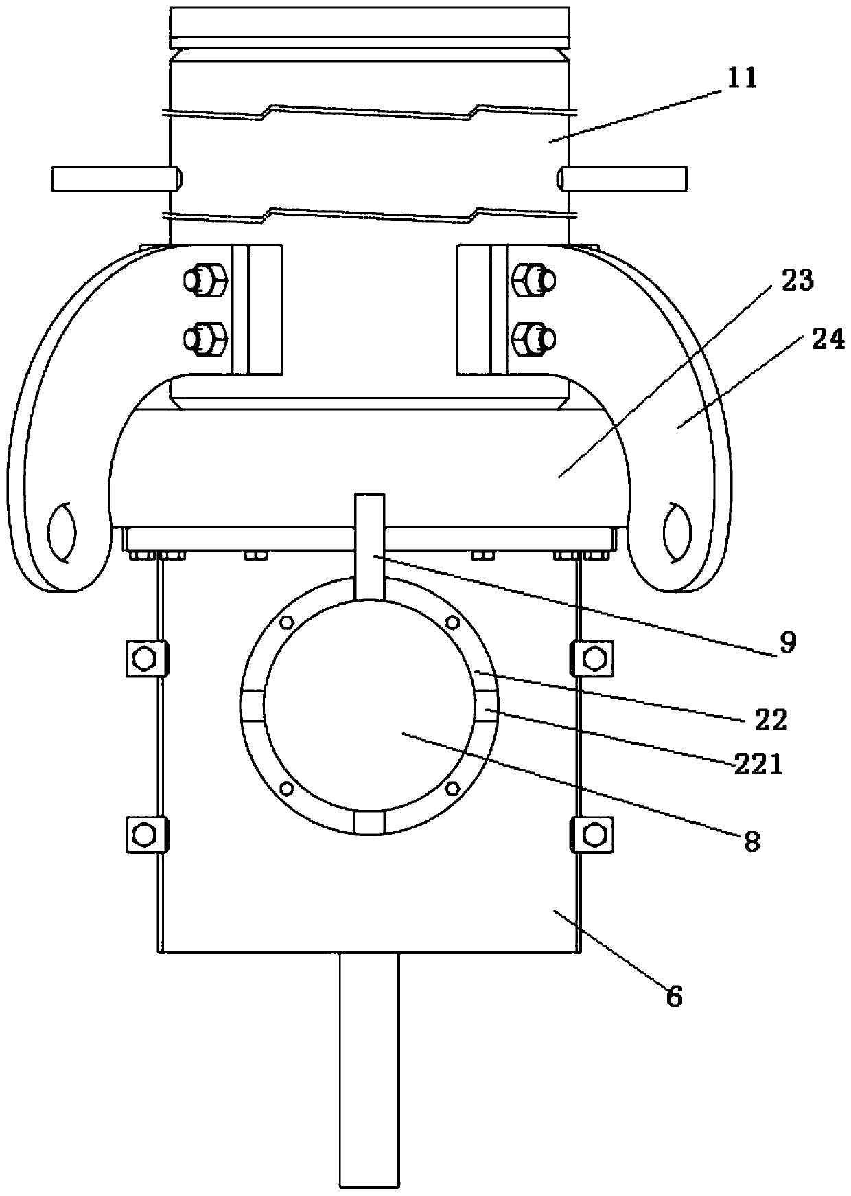
[0057] On the basis of Embodiment 1 or Embodiment 2, specifically, preferably, since a good shielding structure needs to be constructed for the moving shielding rod 1, the shielding structure includes an upper sealing head 23 and a lower sealing head 13, and on the upper sealing head 23. The outer shielding cylinder 11 is used to construct a closed space A17 between the lower heads 13, and the closed space A is filled with radiation shielding material (lead-filled), so as to achieve the shielding of the inner pipe 3, and at the same time set the lower head 13 The positioning device has the functions of positioning and shielding.
[0058] Therefore, the present invention preferably also includes: an upper sealing head 23, a lower sealing head 13, a positioning device is arranged above the lower sealing head 13,
[0059] The hoisting structure also includes an inner tube 3 sleeved outside the moving shielding rod 1, and an outer shielding tube 11 is...
PUM
 Abstract
Description
Claims
Application Information
 - Generate Ideas
- Intellectual Property
- Life Sciences
- Materials
- Tech Scout
- Unparalleled Data Quality
- Higher Quality Content
- 60% Fewer Hallucinations
Browse by: Latest US Patents, China's latest patents, Technical Efficacy Thesaurus, Application Domain, Technology Topic, Popular Technical Reports.
© 2025 PatSnap. All rights reserved.Legal|Privacy policy|Modern Slavery Act Transparency Statement|Sitemap|About US| Contact US: help@patsnap.com