Antenna device and electronic equipment

A technology for antenna devices and electronic equipment, which is applied to antenna supports/installation devices, antenna devices with additional functions, antennas, etc., and can solve the problem of low transmittance, insufficient antenna radiation performance, and 5G millimeter wave signal communication performance. To reduce the impact, improve the communication performance, and increase the bandwidth

Active Publication Date: 2019-12-31
GUANGDONG OPPO MOBILE TELECOMM CORP LTD
View PDF22 Cites 13 Cited by
  • Summary
  • Abstract
  • Description
  • Claims
  • Application Information

AI Technical Summary

Problems solved by technology

Millimeter wave signals are the main means of realizing 5G mobile communication. However, when millimeter wave antennas are applied to electronic equipment, they are usually placed in the storage space inside the electronic equipment, and the millimeter wave signal antenna radiates out through the electronic equipment. The transmittance is low and cannot meet the requirements of antenna radiation performance
Or, the transmittance of external millimeter wave signals penetrating electronic equipment is low
It can be seen that in the prior art, the communication performance of the 5G millimeter wave signal is poor

Method used


Image

  • Antenna device and electronic equipment
  • Antenna device and electronic equipment
  • Antenna device and electronic equipment

Examples


Embodiment Construction

[0044] The technical solutions in the embodiments of the present application will be described clearly and completely in conjunction with the accompanying drawings in the embodiments of the present application. Obviously, the described embodiments are only a part of the embodiments of the present application, rather than all the embodiments. Based on the embodiments in this application, all other embodiments obtained by a person of ordinary skill in the art without creative work shall fall within the protection scope of this application.

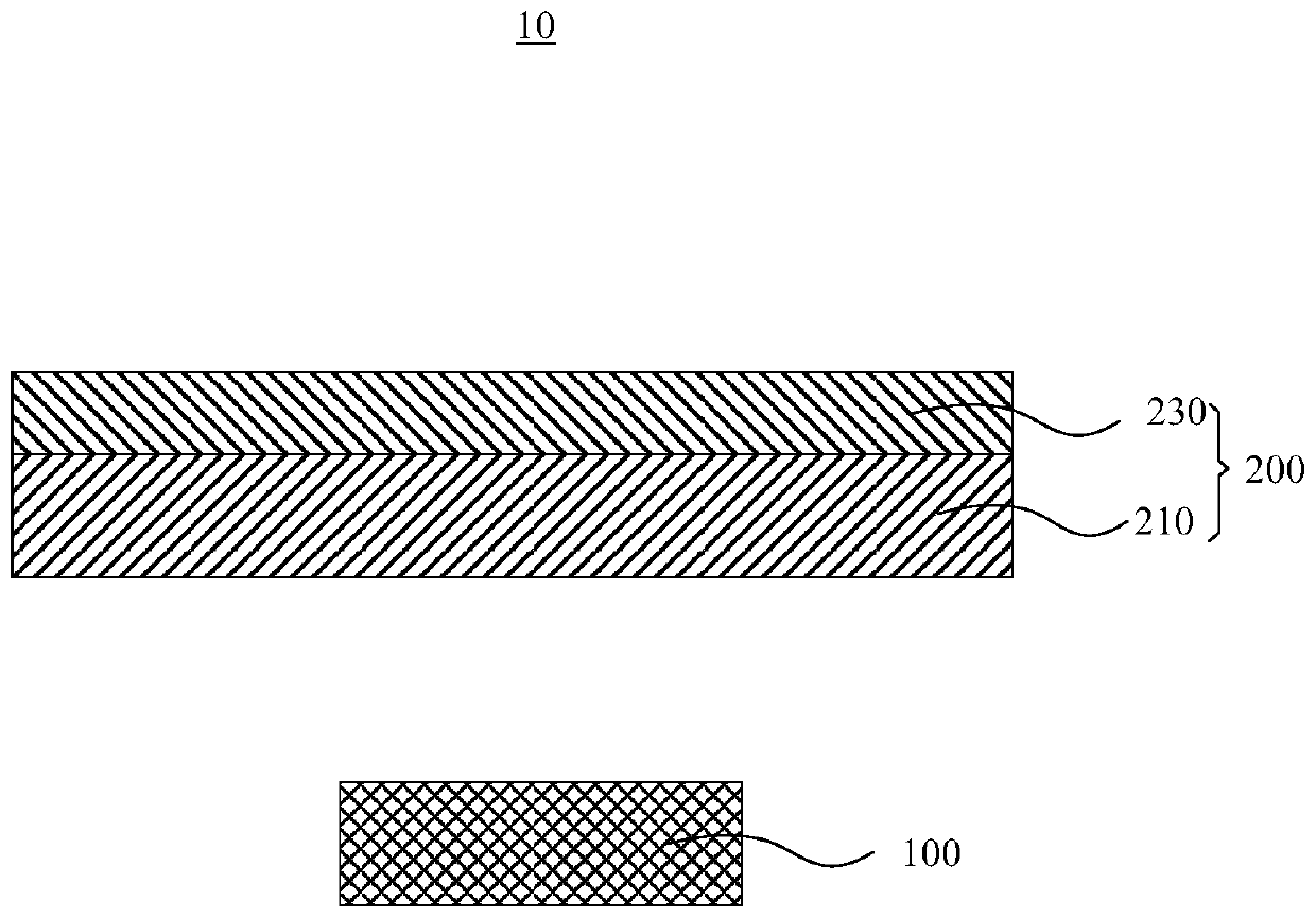
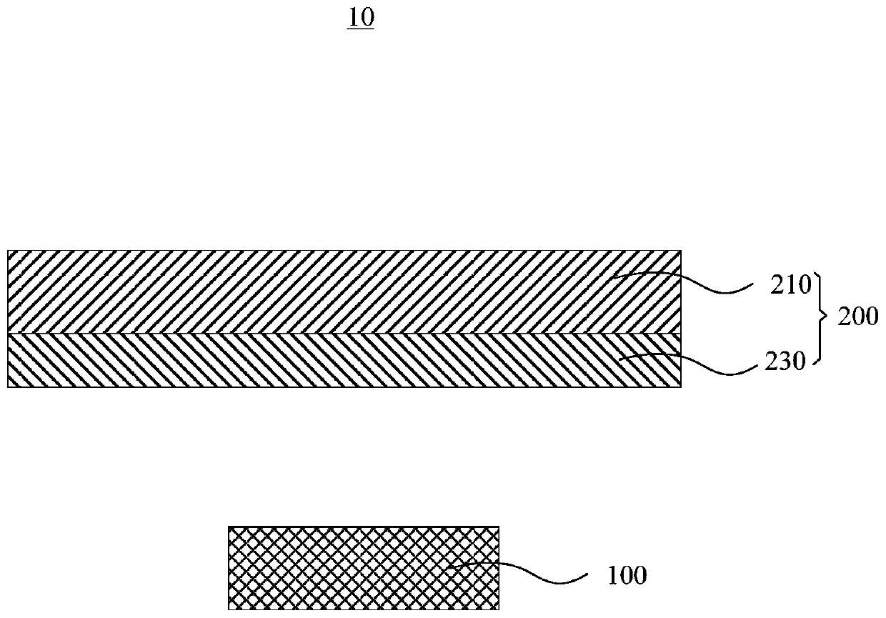
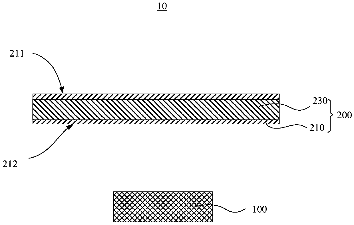
[0045] See figure 1 , figure 1 This is a schematic diagram of the antenna device provided in the first embodiment of this application. The antenna device 10 includes an antenna module 100 and a radome 200. The antenna module 100 is used to transmit and receive radio frequency signals of a predetermined frequency band in a predetermined direction range. The radome 200 and the antenna module 100 are spaced apart, and the radome 200 is located wi...


PUM


Abstract

The present application provides an antenna device and electronic equipment. The antenna device comprises an antenna module and a radome. The antenna module is used for transmitting and receiving radio frequency signals of a preset frequency band towards a preset direction range. The radome is arranged at intervals from the antenna module, and the radome is located within the preset direction range. The radome comprises a substrate and a resonant structure carried on the substrate. The substrate is used for passing the radio frequency signal of the first frequency band in the preset frequencyband. The resonant structure is used for adjusting the passband width of the substrate to the radio frequency signal of the preset frequency band so that the radome can pass the radio frequency signalof the second frequency band in the preset frequency band, wherein the bandwidth of the second frequency band is greater than the bandwidth of the first frequency band, and the radio frequency signalof the second frequency band includes the radio frequency signal of the first frequency band. The antenna device has a large bandwidth, and electronic equipment applying the antenna device has good communication performance.

Description

Technical field [0001] This application relates to the field of electronic equipment, and in particular to an antenna device and electronic equipment. Background technique [0002] With the development of mobile communication technology, the traditional 4th-Generation (4G) mobile communication can no longer meet people's requirements. The fifth-generation (5th-Generation, 5G) mobile communication is favored by users due to its high communication speed. For example, when using 5G mobile communication to transmit data, the transmission speed is hundreds of times faster than that of 4G mobile communication. Millimeter wave signals are the main means to realize 5G mobile communications. However, when millimeter wave antennas are used in electronic equipment, millimeter wave antennas are usually installed in the containment space inside the electronic equipment, and the millimeter wave signal antennas radiate through the electronic equipment. The transmittance is low, which does not...

Claims


Application Information

Patent Timeline
Patent Type & Authority Applications(China)
IPC IPC(8): H01Q1/42H01Q15/00H01Q1/22
CPCH01Q1/42H01Q15/0013H01Q15/0026H01Q15/0093H01Q1/22H01Q1/243H01Q1/425H01Q1/241H01Q1/44
Inventor 贾玉虎
Owner GUANGDONG OPPO MOBILE TELECOMM CORP LTD
Why Eureka
Try Eureka