Temperature sensing optical fiber type power cable joint structure adopting guide cover

A technology of temperature-sensing optical fiber and power cable, which is applied in the direction of cable joints, power cables, and power cables including optical transmission components, etc., and can solve the problem of small curvature radius of temperature-sensing optical fiber, unfavorable installation and installation of temperature-sensing optical fiber, damage to temperature-sensing optical fiber, etc. question

Inactive Publication Date: 2019-12-31
李新荷
View PDF7 Cites 0 Cited by
  • Summary
  • Abstract
  • Description
  • Claims
  • Application Information

AI Technical Summary

Problems solved by technology

In the prior art, the temperature-sensing optical fiber is often installed in the second way, which is to wind the temperature-sensing optical fiber on the outer surface of the copper connecting pipe, but this method will cause the temperature-sensing optical fiber to be wound irregularly and randomly on the copper connecting pipe On the outer surface, it is easy to cause the radius of curvature of the local temperature-sensing optical fiber to be too small, or even damage the temperature-sensing optical fiber, which is not conducive to the installation and installation of the temperature-sensing optical fiber, and the existing cable joints are not well protected, which greatly reduces the cable Effects of use of joints and reduced service life

Method used


Image

  • Temperature sensing optical fiber type power cable joint structure adopting guide cover
  • Temperature sensing optical fiber type power cable joint structure adopting guide cover
  • Temperature sensing optical fiber type power cable joint structure adopting guide cover

Examples


Embodiment Construction

[0025] The following will clearly and completely describe the technical solutions in the embodiments of the present invention with reference to the accompanying drawings in the embodiments of the present invention. Obviously, the described embodiments are only some, not all, embodiments of the present invention.

[0026] In describing the present invention, it should be understood that the terms "upper", "lower", "front", "rear", "left", "right", "top", "bottom", "inner", " The orientation or positional relationship indicated by "outside", etc. is based on the orientation or positional relationship shown in the drawings, and is only for the convenience of describing the present invention and simplifying the description, rather than indicating or implying that the referred device or element must have a specific orientation, so as to Specific orientation configurations and operations, therefore, are not to be construed as limitations on the invention.

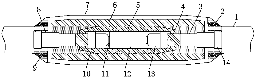
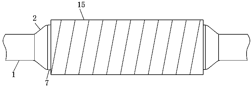
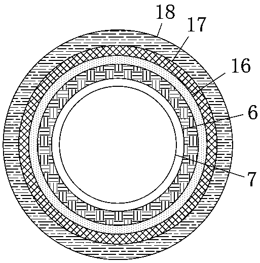
[0027] refer to Figure ...


PUM


Abstract

The invention discloses a temperature sensing optical fiber type power cable joint structure adopting a guide cover, which comprises two cables. A plurality of filling tubes are arranged in the cable;an insulating sheath is arranged in the cable; a plurality of power lines are arranged in the insulating sheath; a loose tube is arranged in the cable; a temperature sensing optical fiber is arrangedin the loose tube; a sleeve filler is arranged between the loose tube and the temperature sensing optical fiber; the end of the cable is sleeved with a steel armor, an end protective layer, a coppershielding layer, an outer semiconducting layer and a wire core insulating layer; and the steel armor is located at the rear end of the end of the cable. The structure is reasonably designed, the situation in which the temperature sensing optical fiber is irregularly and randomly wound on the outer surface of a copper connecting pipe, and consequently the curvature radius of the local temperature sensing optical fiber is too small or the optical fiber is damaged can be effectively avoided, the protection safety performance of the cable joint is greatly improved, and the using effect of the cable joint is improved.

Description

technical field [0001] The invention relates to the technical field of power cable joint structures, in particular to a temperature-sensitive optical fiber type power cable joint structure using a guide cover. Background technique [0002] The cable joint is also called the cable head. After the cable is laid, in order to make it a continuous line, each section of the line must be connected as a whole, and these connection points are called cable joints. The cable joints in the middle of the cable line are called intermediate joints, and the cable joints at both ends of the line are called terminal heads. The cable joint is used to lock and fix the incoming and outgoing lines, and play the role of waterproof, dustproof and shockproof. [0003] At present, temperature-sensing optical fiber power cables are more and more widely used in daily life. This kind of cable can monitor the actual temperature of the conductor when the cable is running through the temperature-sensing ...

Claims


Application Information

Patent Timeline
Patent Type & Authority Applications(China)
IPC IPC(8): H02G15/18H01B9/00H01B7/32
CPCH01B7/324H01B9/005H02G15/18
Inventor 李新荷
Owner 李新荷
Why Eureka
Try Eureka