SiC MOSFET short-circuit protection circuit and method based on short-circuit current suppression

A short-circuit protection circuit and short-circuit current technology, applied in circuits, electrical components, electronic switches, etc., can solve the problems of prolonged short-circuit fault duration, increased drain breakdown, increased short-circuit power device impact, etc., to ensure a normal turn-on rate. , the effect of reducing turn-off loss and reducing overvoltage spikes

Active Publication Date: 2019-12-31
CHAJNA MAJNING DRAJVS EHND AUTOMEHJSHN KO
View PDF11 Cites 11 Cited by
  • Summary
  • Abstract
  • Description
  • Claims
  • Application Information

AI Technical Summary

Problems solved by technology

At present, the most commonly used short-circuit protection circuit is based on the detection method of the drain voltage. The circuit of this method is the simplest, but when a type of short-circuit occurs, in order to avoid false alarms, a longer blanking time is usually set, resulting in continuous short-circuit faults. The time is extended, and when the second type of short circuit occurs, the filter capacitor in the short circuit detection circuit will also increase the detection time. Therefore, when this circuit is used, the short circuit loss is high, which increases the impact of the short circuit power device. In addition, when it is turned off Excessive short-circuit current will increase the overvoltage spike on the drain, increasing the risk of drain breakdown

Method used


Image

  • SiC MOSFET short-circuit protection circuit and method based on short-circuit current suppression
  • SiC MOSFET short-circuit protection circuit and method based on short-circuit current suppression
  • SiC MOSFET short-circuit protection circuit and method based on short-circuit current suppression

Examples


Embodiment

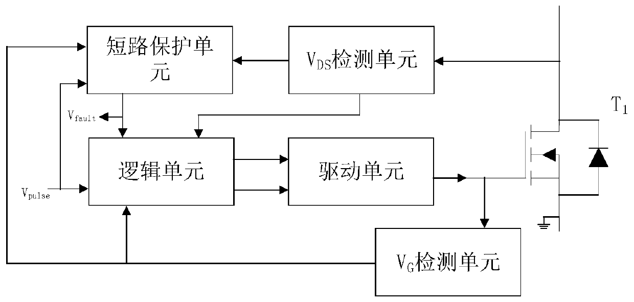
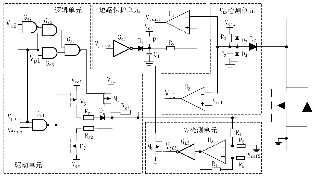
[0030] Embodiment: A SiC MOSFET short-circuit protection circuit and method based on short-circuit current suppression, comprising: a logic unit, a driving unit, a short-circuit protection unit, a V DS detection unit and V G The detection unit, wherein: the first input terminal of the logic unit and the first input terminal of the short-circuit protection unit are connected to the driving signal V pulse , the second input terminal of the logic unit is connected to the first output terminal of the short-circuit protection unit, and outputs a fault signal V pulse , the third input of the logic unit is connected to V DS The first output terminal of the detection unit is connected to the fourth input terminal of the logic unit with V G The first output terminal of the detection unit and the second input terminal of the short-circuit protection unit are connected, the first output terminal and the second output terminal of the logic unit are respectively connected with the first ...


PUM


Abstract

The invention provides a SiC MOSFET short-circuit protection circuit and method based on short-circuit current suppression. The short-circuit protection circuit comprises a logic unit, a driving unit,a short-circuit protection unit, a VDS detection unit and a VG detection unit, and short-circuit current is suppressed by adopting a method of reducing gate voltage VG, so that impact of a short-circuit fault on a device is reduced, short-circuit loss is reduced, and short-circuit tolerance time is prolonged. When a type of short circuit occurs in the SiC MOSFET, the drain voltage VDS does not drop to the conduction voltage drop, and the gate driving voltage in the switching-on transient state is selected by judging whether the drain voltage VDS drops to the conduction voltage drop or not, sothat the gate voltage VG is clamped at a relatively low driving voltage level; when the SiC MOSFETs are subjected to a second-class short circuit, the gate voltage VG will change suddenly, and then avoltage spike is formed. According to the invention, the gate driving voltage in the conduction state is selected by judging whether the gate voltage VG in the conduction state has the voltage spikeor not, so that the gate voltage VG can be clamped at a lower driving voltage level during short circuit; and, in addition, the circuit provided by the invention does not influence the normal switching-on process, and ensures the rapidity of the switching-on transient state of the SiC MOSFET.

Description

technical field [0001] The invention relates to a SiC MOSFET short-circuit protection circuit and method based on short-circuit current suppression, belonging to the technical field of power electronics. Background technique [0002] Silicon carbide (SiC), as a new type of wide-bandgap semiconductor material, is attracting more and more attention in the power electronics industry due to its excellent physical and electrical properties. As the third generation of power semiconductor devices, SiC power devices will become the dominant device for future power converters. Due to its low on-resistance, high switching rate and other performance advantages, SiC MOSFET is considered to be the most likely to replace the currently widely used Si IGBT. However, in practical engineering applications, its high gate voltage makes the short-circuit current of SiC MOSFET will decrease It will reach nearly ten times the rated current, which makes the short-circuit loss and junction temperat...

Claims


Application Information

Patent Timeline
Patent Type & Authority Applications(China)
IPC IPC(8): H03K17/0812H03K17/687
CPCH03K17/08122H03K17/687
Inventor 谭国俊张经纬耿程飞何凤有
Owner CHAJNA MAJNING DRAJVS EHND AUTOMEHJSHN KO
Why Eureka
Try Eureka