Optical network device and optical module

An optical network, the first technology, applied in optical fiber transmission, optical fiber radio, optical multiplexing system, etc., can solve the problems of high cost, large number of optical transmitters and optical receivers, etc.

Active Publication Date: 2019-12-31
HUAWEI TECH CO LTD
View PDF3 Cites 2 Cited by
  • Summary
  • Abstract
  • Description
  • Claims
  • Application Information

AI Technical Summary

Problems solved by technology

[0003] However, the cost of optical network equipment is mainly reflected in optical transmitters and optical receivers. Currently, in order to support optical interfaces above 100GE, there are four optical transmitters and optical receivers in optical network equipment. The number of optical transmitters and optical receivers is large, and the cost is high

Method used


Image

  • Optical network device and optical module
  • Optical network device and optical module
  • Optical network device and optical module

Examples


Embodiment Construction

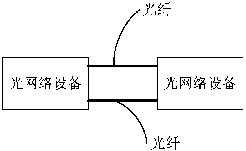
[0093] figure 1 A schematic structural diagram of the communication system provided by the embodiment of this application, such as figure 1 As shown, the communication system in this embodiment includes two optical network devices, the two optical network devices are connected through optical fibers, and optical signals are transmitted between each other through optical fibers, figure 1 Two optical fibers are used as an example, but this embodiment is not limited thereto. Optical network devices include but are not limited to the following: switches, routers, packet transport network (Packet Transport Network, PTN) devices, and transmission devices.

[0094]Wherein, the optical network device mentioned below may be the above-mentioned optical network equipment or may be a component of the above-mentioned optical network equipment.

[0095] The terminology mentioned in this application is explained below.

[0096] CAUI-4 interface: an optional interface for the PMA sublayer ...


PUM


Abstract

The embodiment of the invention provides an optical network device and an optical module. The optical network device comprises a processing chip, a first optical transmission assembly and a second optical transmission assembly, the processing chip is used for receiving N electric signals sent by the single board interface chip, N is an integer larger than 2, and the received N electric signals areconverted into two electric signals which are expressed as a first electric signal and a second electric signal respectively. Respectively sending the first electric signal and the second electric signal to a first optical transmission assembly and a second optical transmission assembly; the first optical transmission assembly is used for converting the first electric signal into a first opticalsignal; the second optical transmission assembly is used for converting the second electric signal into a second optical signal. Since the N to-be-sent electric signals acquired by the processing chipare combined, only two optical transmission assemblies are connected with the processing chip, the processing chip does not need to be connected with four optical transmission assemblies, the numberof the optical transmission assemblies is reduced, and the cost is reduced.

Description

technical field [0001] The embodiments of the present application relate to the field of communication technologies, and in particular, to an optical network device and an optical module. Background technique [0002] With the advent of the 5G era, the demand for network bandwidth is getting higher and higher, and high-speed interfaces such as 100GE interfaces, 200GE interfaces, and 400GE interfaces are more and more widely used. Taking the 100GE interface as an example, in order to realize the communication of the 100GE interface, in the sending direction, the optical network equipment uses 4 optical transmitters (Optical Transmitter), and the non-return to zero code (Non-Retum to Zero, NRZ) code is used to realize The 4*25.78125G electrical signal is converted into an optical signal, and then multiplexed through oMUX, that is, the four 4*25.78125G optical signals are transmitted through the same optical fiber. In the receiving direction, the optical network equipment rece...

Claims


Application Information

Patent Timeline
IPC IPC(8): H04B10/2575H04B10/25H04J14/02
CPCH04B10/25752H04J14/0279H04B2210/006H04B10/25891H04B10/2589H04B10/2575H04J14/0256H04B10/40H04B10/2507
Inventor 陈国导
Owner HUAWEI TECH CO LTD
Why Eureka
Try Eureka