
Automatic temperature measuring thermos bottle stopper protection device

A protection device, a thermos technology, which is applied to heat-insulating utensils, kitchen utensils, household utensils, etc., can solve problems such as bottle stopper falling, high-temperature liquid dust particle pollution, inconvenient use, etc. Balanced, easy-to-use effects

Active Publication Date: 2020-12-15
ZHEJIANG LAISIAO ELECTRIC
View PDF8 Cites 0 Cited by
  • Summary
  • Abstract
  • Description
  • Claims
  • Application Information

AI Technical Summary

Problems solved by technology

[0003] At present, most of the mouths of existing thermos bottles are made of wood plugs. Because most of the interior of the thermos bottles are high-temperature liquids, when they are first put into the thermos bottle, the hot air will be poured into the limited space with the hot water, and the water vapor will With the high temperature, it will expand, so that the internal pressure of the thermos bottle is greater than the external pressure, so that the cork will be pushed out, causing the cork to fall and the function of sealing and heat preservation cannot be performed, so that the high temperature liquid cannot be kept warm, and it will also lead to high temperature. The liquid is polluted by dust particles in the air. In addition, when the temperature of the liquid in the thermos bottle drops, the originally thermally expanded gas will shrink due to the temperature drop, resulting in a decrease in its volume, and the inner cavity of the thermos bottle will form a negative pressure state, making the bottle The plug is sucked and it is difficult to open, which is very inconvenient for people to use

Method used


Image

  • Automatic temperature measuring thermos bottle stopper protection device
  • Automatic temperature measuring thermos bottle stopper protection device
  • Automatic temperature measuring thermos bottle stopper protection device

Examples


Embodiment Construction

[0019] The following will clearly and completely describe the technical solutions in the embodiments of the present invention with reference to the accompanying drawings in the embodiments of the present invention. Obviously, the described embodiments are only some, not all, embodiments of the present invention. Based on the embodiments of the present invention, all other embodiments obtained by persons of ordinary skill in the art without making creative efforts belong to the protection scope of the present invention.

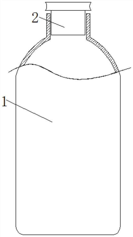
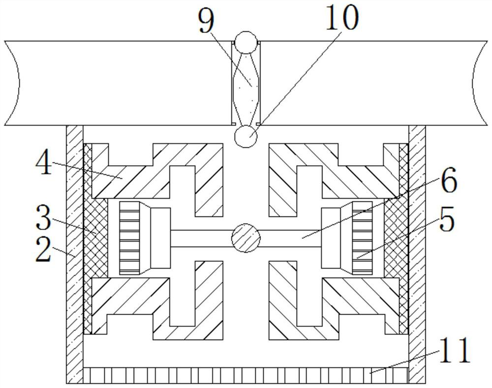
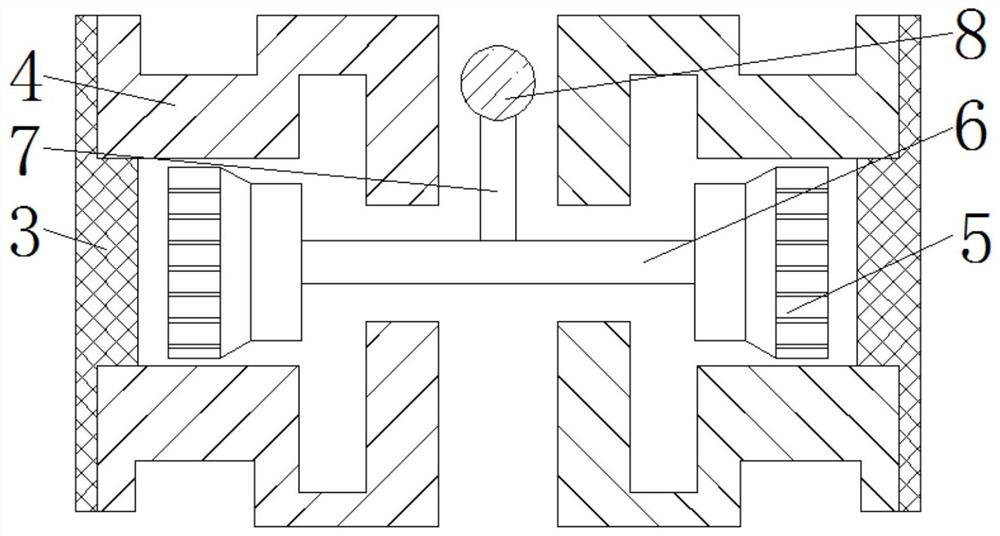
[0020] see Figure 1-4 , the automatic temperature measuring thermos bottle stopper protection device, including: bottle body 1, the upper end of bottle body 1 is movably installed with bottle stopper 2 body, the upper end of bottle stopper body 2 is fixedly installed with stopper, the diameter of stopper is larger than the upper end interface of bottle body 1 The diameter of the part is mainly to prevent the cork body 2 from falling into the bottle body 1, an...


PUM


Abstract

The invention relates to the technical field of vacuum bottles, and discloses an automatic temperature measuring vacuum bottle stopper protection device. The device comprises a bottle body; a bottle stopper body is movably mounted at the upper end of the bottle body; two symmetrical display blocks are fixedly mounted on the inner side walls of the bottle stopper body; two symmetrical connecting blocks are fixedly mounted on the opposite sides of the display blocks; temperature measuring blocks are fixedly mounted in the connecting blocks; a connecting rod is movably mounted between the two temperature measuring blocks; a magnetic rod is fixedly mounted on the front surface of the connecting rod; an air bag is fixedly mounted at the front end of the magnetic rod; a flat pressing block is mounted on the upper surface of the bottle stopper body in a sliding manner; the lower end of the flat pressing block penetrates through and extends to the interior of the bottle stopper body and is fixedly provided with a magnetic ball; and a vent plate is fixedly mounted at the lower end of the bottle stopper body. Through cooperative use of the display blocks, the connecting block and the temperature measuring blocks, the temperature in the bottle body can be measured at any time, so that people can observe the temperature in the bottle body at any time.

Description

technical field [0001] The invention relates to the technical field of thermos bottles, in particular to an automatic temperature-measuring thermos bottle stopper protection device. Background technique [0002] A thermos bottle, also called a thermos bottle, uses heat radiation to refract heat back. It is a container used to hold high-temperature liquids and has good heat preservation performance; the thermos bottle mainly uses the inner tank for liquid storage and insulation. It is coated with a layer of thermal insulation coating, which can reflect the heat radiation of the high-temperature liquid in full bloom, so as to avoid the loss of heat. Insulation effect. [0003] At present, most of the mouths of existing thermos bottles are made of wood plugs. Because most of the interior of the thermos bottles are high-temperature liquids, when they are first put into the thermos bottle, the hot air will be poured into the limited space with the hot water, and the water vapor ...

Claims


Application Information

Patent Timeline
Patent Type & Authority Patents(China)
IPC IPC(8): A47J41/00
CPCA47J41/0083A47J41/0094
Inventor 郭司航
Owner ZHEJIANG LAISIAO ELECTRIC
Learn More