Adjustable clamping mechanism for gear chamfering processing and clamping method thereof

A clamping mechanism and adjustable technology, which is applied in the direction of gear cutting machines, metal processing equipment, gear tooth manufacturing devices, etc., can solve the problems of reduced practicality of the clamping mechanism, inconvenient adjustment, slow progress, etc., to speed up the processing progress and improve The effect of practicality

Pending Publication Date: 2020-01-03
盐城永安科技有限公司
View PDF0 Cites 4 Cited by
  • Summary
  • Abstract
  • Description
  • Claims
  • Application Information

AI Technical Summary

Problems solved by technology

[0004] The object of the present invention is to provide an adjustable clamping mechanism and clamping method for gear chamfering processing, in order to solve the problem that the current clamping mechanism on the market proposed by the above-mentioned background technology is inconvenient to adjust according to the diameter of the gear. When chamfering gears with different diameters, replace different types of clamping mechanisms, which not only slows down the progress, but also increases the workload of the staff, and it is not easy to adjust and fix according to the thickness of the gears, which leads to the practicability of the clamping mechanism Lowering the problem

Method used


Image

  • Adjustable clamping mechanism for gear chamfering processing and clamping method thereof
  • Adjustable clamping mechanism for gear chamfering processing and clamping method thereof
  • Adjustable clamping mechanism for gear chamfering processing and clamping method thereof

Examples


Embodiment Construction

[0021] The following will clearly and completely describe the technical solutions in the embodiments of the present invention with reference to the accompanying drawings in the embodiments of the present invention. Obviously, the described embodiments are only some, not all, embodiments of the present invention. Based on the embodiments of the present invention, all other embodiments obtained by persons of ordinary skill in the art without making creative efforts belong to the protection scope of the present invention.

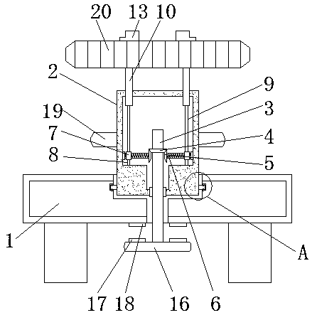
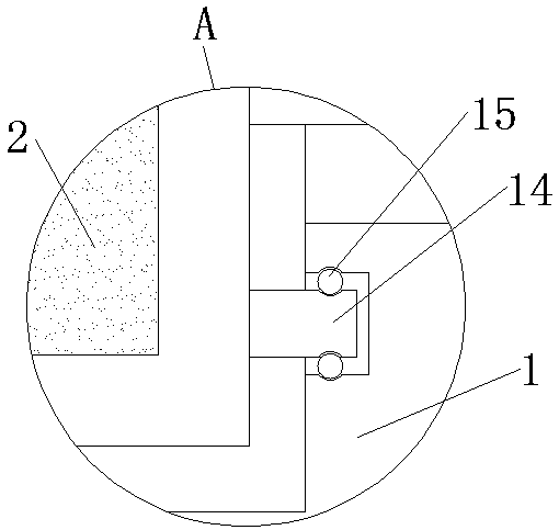
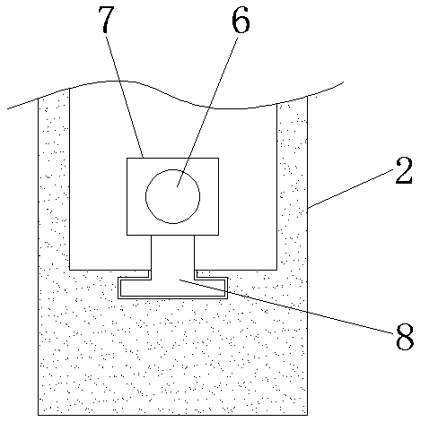
[0022] see Figure 1-5 , the present invention provides a technical solution: an adjustable clamping mechanism for gear chamfering, including a base 1, a column 2, a rotating rod 3, a first bevel gear 4, a second bevel gear 5, and a screw rod 6 , connecting rod 7, connecting plate 8, vertical plate 9, support plate 10, first clamping block 11, elastic spring 12, second clamping block 13, clamping block 14, ball 15, handle 16, first magnet 17, the second Two m...


PUM


Abstract

The invention discloses an adjustable clamping mechanism for gear chamfering processing and a clamping method thereof. The adjustable clamping mechanism for the gear chamfering processing comprises abottom seat, a vertical plate, a clamp block and a gear body, wherein a vertical pillar is arranged above the bottom seat, a rotary rod is arranged in the vertical pillar, a first bevel gear is fixedon the outer wall of the rotary rod, a second bevel gear is connected onto the outer wall of the first bevel gear in a meshing mode, a lead screw runs through the interior of the second bevel gear, the top of a first clamping block is connected with a second clamping block through an elastic force spring, a dial block is arranged on the outer wall of the middle of the vertical pillar, and the gearbody is arranged on the outer sides of the first clamping block and the second clamping block. According to the adjustable clamping mechanism for the gear chamfering processing, the elastic force spring is arranged between the first clamping block and the second clamping block, and the first clamping block and the second clamping block are both in an L shape, and then can clamp and fix gears different in thickness, improve practicability of the clamping mechanism, and quicken processing progress of the gear chamfering.

Description

technical field [0001] The invention relates to the technical field of gear chamfering processing, in particular to an adjustable clamping mechanism and clamping method for gear chamfering processing. Background technique [0002] Gear chamfering refers to chamfering and rounding the ends of the gear teeth to make the gear more convenient and practical during use. Usually, the gear chamfering process needs to be fixed, so a clamping mechanism is required. [0003] However, the existing clamping mechanism still has some deficiencies during use. For example, it is not convenient to adjust according to the diameter of the gear. The traditional way is to replace different types of clamping mechanisms when chamfering gears with different diameters. This not only The slow progress also increases the workload of the staff, and it is not convenient to adjust and fix according to the thickness of the gear, which leads to the reduction of the practicability of the clamping mechanism, ...

Claims


Application Information

Patent Timeline
Patent Type & Authority Applications(China)
IPC IPC(8): B23F23/06
CPCB23F23/06
Inventor 张元张津王俊棋于广滨
Owner 盐城永安科技有限公司
Why Eureka
Try Eureka