Cooking equipment
A technology of cooking equipment and components, which is applied in the field of cooking equipment, can solve the problems of inability to realize "infinite" gear adjustment, poor stuck feel, complex structure, etc., and achieve the effect of user-friendly manipulation, convenient operation, and simple operation mode
- Summary
- Abstract
- Description
- Claims
- Application Information
AI Technical Summary
Problems solved by technology
Method used
Image
Examples
Embodiment 1
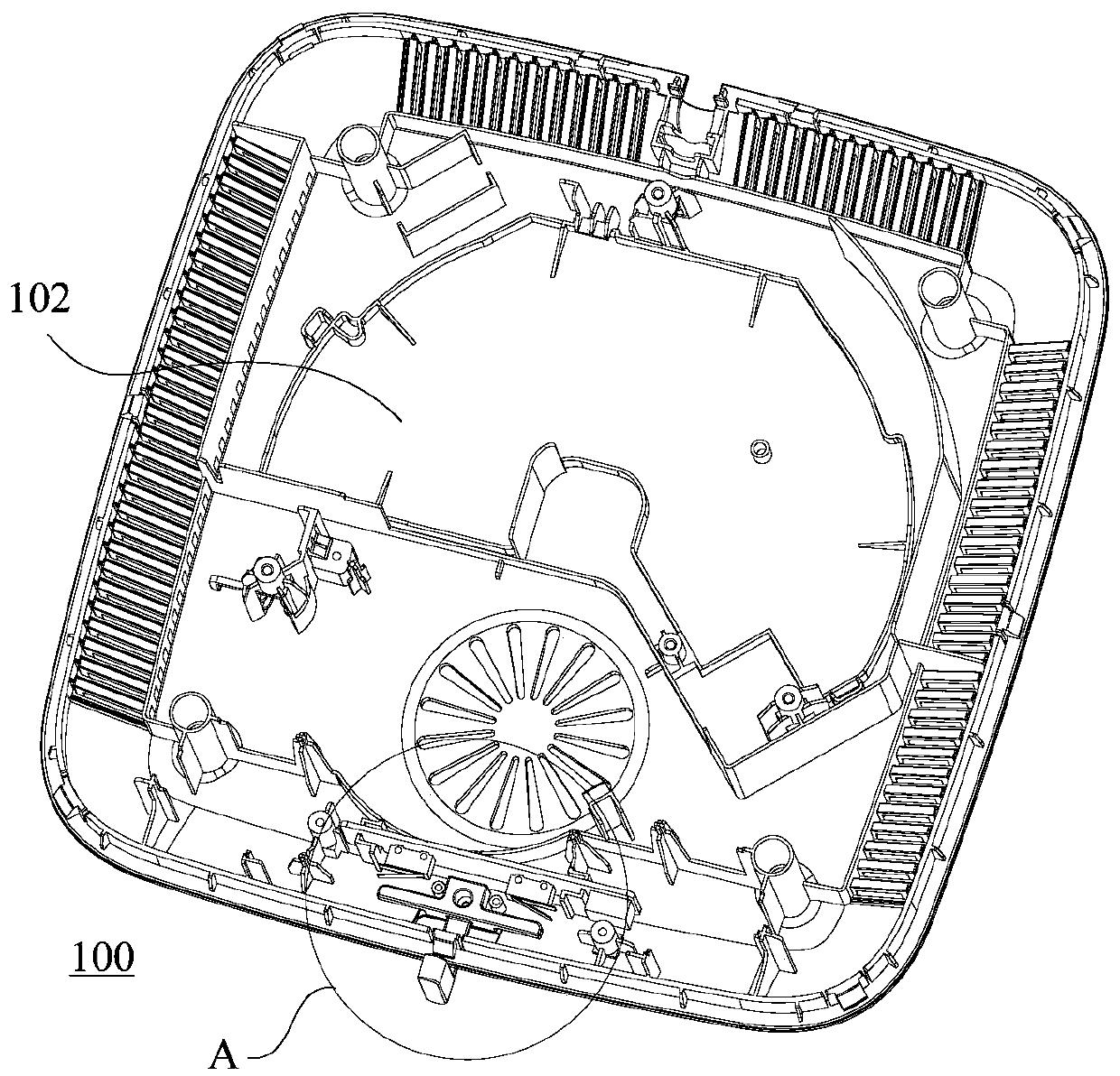
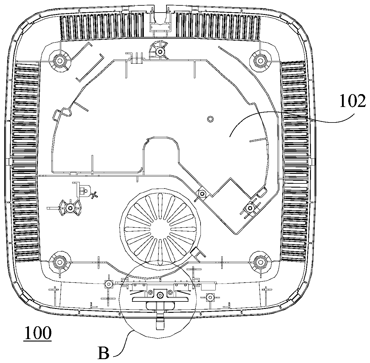
[0082] Such as Figure 1 to Figure 14 As shown, the first embodiment of the present invention proposes a cooking device 100, including: a housing 102, a response component (not shown in the figure, but both the first response component 1042 and the second response component 1044 are response components) , a heating element (not shown in the figure) and a toggle component 106 .
[0083] Specifically, the toggle member 106 has a trigger portion, and the toggle member 106 can swing relative to the casing 102 . In the process of toggling the part 106, the trigger part can touch the response part during the swinging process of the toggling part 106, and then release the response part during the swinging process of the toggling part 106; the response part detects the touch or release action of the trigger part Afterwards, a corresponding signal is sent out according to the touch or release action to respond, so that the control component (ie, the circuit board 118 ) connected to th...
Embodiment 2
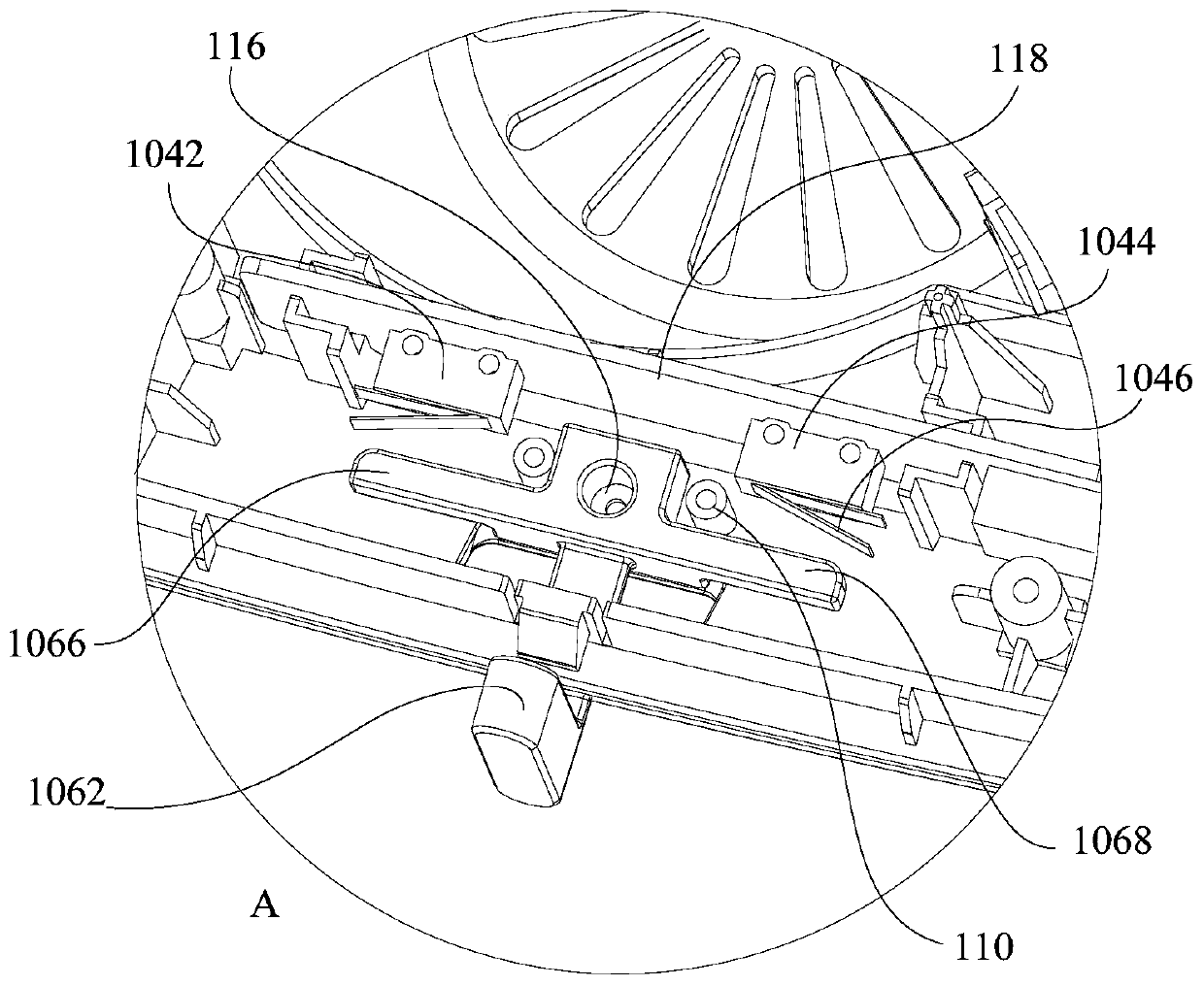
[0092] Such as figure 1 and figure 2 As shown, the second embodiment of the present invention proposes a cooking device 100 , including: a housing 102 , a first response component 1042 , a second response component 1044 , a toggle component 106 and a stopper structure 110 .
[0093] Specifically, as figure 2 As shown, the toggle member 106 includes interconnected levers 1062 and lever arms 1064, the lever arms 1064 and the levers 1062 are alternately arranged, the levers 1062 are arranged toward the direction extending from the housing 102, and the lever arms 1064 are arranged along the first The distribution direction of the first response component 1042 and the second response component 1044 is extended; the toggle component 106 is installed on the housing 102 through the connecting piece 116 to realize the rotational connection with the housing 102; the lever 1062 can swing relative to the housing 102 , a trigger portion is formed on the lever arm 1064 , and the trigger...
Embodiment 3
[0103] Such as Figure 3 to Figure 6 As shown, the third embodiment of the present invention proposes a cooking device 100, including: a housing 102, a first response component 1042, a second response component 1044, a toggle component 106, a stopper structure 110 and an elastic reset member 108 .
[0104] The difference between this embodiment and the second embodiment lies in the addition of an elastic reset member 108 . Among them, such as Figure 4 and Figure 6 As shown, the elastic reset member 108 is disposed between the toggle member 106 and the response member, and defines the positional relationship among the toggle member 106 , the response member and the elastic reset member 108 .
[0105] When the toggle part 106 touches the response part, the elastic reset part 108 is in a compressed state driven by the external force of the toggle part 106; In response to separation of the parts, the micro-movement part is released and returned to the original position.
[...
PUM
 Abstract
Description
Claims
Application Information
 - R&D
- Intellectual Property
- Life Sciences
- Materials
- Tech Scout
- Unparalleled Data Quality
- Higher Quality Content
- 60% Fewer Hallucinations
Browse by: Latest US Patents, China's latest patents, Technical Efficacy Thesaurus, Application Domain, Technology Topic, Popular Technical Reports.
© 2025 PatSnap. All rights reserved.Legal|Privacy policy|Modern Slavery Act Transparency Statement|Sitemap|About US| Contact US: help@patsnap.com


